| ID |
Date |
Author |
Type |
Category |
Subject |
|
394
|
Fri Jul 5 14:12:32 2024 |
Liu | Update | Interferometer Simulations | CE BS Mechanical Resonances |
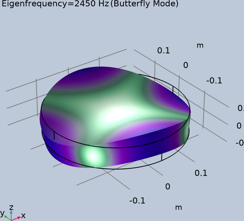
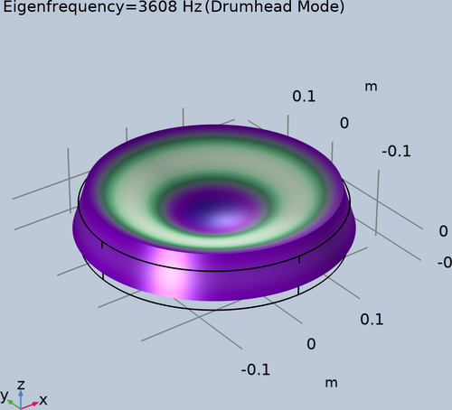
| The butterfly and drumhead mechanical modes for the aLIGO BS were calculated in COMSOL. The resonant frequencies for the two acoustic modes are 2.45 kHz and 3.61 kHz, matching the results in reference for instance.
For a quick projection for the resonant frequencies going from aLIGO to CE, the height and width of the BS are increased assuming the mass is increased from 14 kg to 70 kg, while keeping the aspect ratio fixed. The resonant frequencies for the two mechanical modes as a result becomes smaller, to 1.43 kHz and 2.11 kHz respectively, risking getting in the detection band.
Next step is to implement a mechanical ring with high stiffness outside the BS barrel to combat the decrement of the resonant frequencies of the relevant mechanical modes. |
| Attachment 1: butterfly.png
|
|
| Attachment 2: drumhead.png
|
|
|
395
|
Fri Jul 5 14:23:13 2024 |
Liu | Update | Interferometer Simulations | Engineering drawings for straight edge heater element designs for FROSTI |
| Step files and engineering drawings for the straight edge heater element designs have been created in COMSOL and SolidWorks. They are available in the group Git Repo. With those, we will initiate a discussion with the ceramics supplier for an estimate of the feasibility and benefits of the straight edge element over the curved element in terms of manufacturing cost and time. |
|
404
|
Mon Jul 15 09:36:44 2024 |
Liu | Update | Interferometer Simulations | ETM Profile Optimization for FROSTI |
This is to optimize the FROSTI heating profile for ETM, by minimizing the residual RMSE of the HR surface deformation after the beam size weighted curvature is removed by the current RH. The parameters of the profile being explored are the location, width, and total power for the Gaussian Annulus. As shown in the attached series of plots, the optimal location is 9.9 cm, with a width of 7.7 cm, and a total FROSTI power of 12.7 W (for 1 W of Gaussian beam absorption). The residual RMSE is 1.2 nm. About 0.5% of the FROSTI power is lost at the edges of the TM.
For comparison, without FROSTI, the residual RMSE after the beam size weighted curvature removed by the current RH is 44.5 nm. When the width of the Annulus is set to be 3 cm however, the residual RMS is 3.1 nm, with much smaller FROSTI power needed at 4.7 W, and less power loss at 0.02%. |
| Attachment 1: pdf_merged.pdf
|

|
|
413
|
Mon Jul 29 12:18:52 2024 |
Liu | Update | Interferometer Simulations | Update on FROSTI O5 ETM profile optimization |
| Update on FROSTI O5 ETM profile optimization is attached. |
| Attachment 1: pdf_merged.pdf
|

|
|
414
|
Mon Jul 29 12:20:56 2024 |
Liu | Update | Interferometer Simulations | Update on wavefront actuation with astigmatically driven RH for CE |
| Update on wavefront actuation with astigmatically driven RH for CE is attached. |
| Attachment 1: SURF_nonastig_merged.pdf
|

|
|
415
|
Mon Jul 29 12:23:10 2024 |
Liu | Update | Interferometer Simulations | Update on mechanical resonances of CE BS with stiffener ring |
| Update on mechanical resonances of CE BS with stiffener ring is attached. |
| Attachment 1: eigen_freqs_merged.pdf
|

|
|
455
|
Wed Oct 2 14:49:59 2024 |
Liu | Update | | FROSTI ETM actuation |
| Proposed FROSTI ETM actuation on the HOM7 resonance.
Animation |
|
460
|
Wed Oct 16 14:13:31 2024 |
Liu | Update | | FROSTI with non uniform absorption scattering sources |
| Slides |
|
469
|
Wed Nov 6 13:48:55 2024 |
Liu | Update | Interferometer Simulations | QN modeling update |
| Slides |
|
545
|
Tue Apr 1 11:47:08 2025 |
Liu | Update | | |
|
| Attachment 1: Thermal_state_decoder_update.pdf
|

|
|
549
|
Tue Apr 8 10:47:10 2025 |
Liu | Update | General | Test Mass Thermal State Decoder Update |
|
| Attachment 1: Update.pdf
|

|
|
552
|
Tue Apr 15 11:09:37 2025 |
Liu | Update | FLIR | Test Mass Thermal State Decoder Update with robustness study |
|
| Attachment 1: Update.pdf
|

|
| Attachment 2: Update.pdf
|

|
|
555
|
Thu Apr 17 12:12:29 2025 |
Liu | HowTo | Interferometer Simulations | Preventing Thread Contention in Multiprocessing with Finesse and Cython |
Avoiding Thread Contention When Using Multiprocessing with Finesse and Cython
When running Monte Carlo simulations or other computational workloads, it's common to use Python's ProcessPoolExecutor to parallelize multiple independent tasks. This approach works well—until it interacts with low-level libraries that themselves use multi-threading under the hood.
The Problem: Thread Over-Subscription
In a recent project, I ran into a significant performance issue while executing a large number of Monte Carlo trials using a process pool with 30 worker processes on Megatron (with 48 cores). Each trial ran a function that internally used cython.parallel.prange for fast, element-wise operations, which is what Finesse uses under the hood for many internal numerical calculations. Cython, via OpenMP, was configured to use all available CPU threads per process by default.
This resulted in severe thread over-subscription. With 30 parallel processes and each process attempting to use all 48 threads, the system was launching over 1,400 threads concurrently. The CPU quickly became saturated, and the tasks stalled. In some cases, the system became unresponsive, and the jobs had to be canceled repeatedly.
This happens because when the function calls into these libraries from within a Python multiprocessing context, each subprocess will attempt to use the full number of threads available to the machine.
The Solution: Limit Threads per Process
The solution is simple: explicitly limit the number of threads each subprocess is allowed to use. This can be done by setting the environment variable at the top of your script, before importing any thread-hungry libraries like Finesse.
import os
os.environ["OMP_NUM_THREADS"] = "1"
By setting OMP_NUM_THREADS to "1", we ensure that each multiprocessing worker uses only one thread internally, preventing them from overloading the system and allowing the tasks to run more efficiently.
|
|
558
|
Tue Apr 22 11:04:31 2025 |
Liu | Update | Interferometer Simulations | Test Mass Thermal State Decoder Update with Interferometer Operation |
|
| Attachment 1: Update.pdf
|

|
|
564
|
Tue Apr 29 10:59:25 2025 |
Liu | Update | Interferometer Simulations | Test Mass Thermal State Decoder with Updated Comparison Cases |
|
| Attachment 1: Update.pdf
|

|
|
598
|
Tue Jun 24 13:47:58 2025 |
Liu | Update | Interferometer Simulations | Alternative FROSTI A# optimization approach |
| Alternative FROSTI A# optimization approach |
| Attachment 1: Update.pdf
|

|
|
616
|
Tue Jul 29 11:27:57 2025 |
Liu | Update | Interferometer Simulations | Multi-ring FROSTI optimization for A# |
|
| Attachment 1: Update.pdf
|

|
| Attachment 2: scene-export-temp.html
|
| Attachment 3: scene-export-deformation.html
|
|
622
|
Tue Aug 5 12:21:04 2025 |
Liu | Update | Interferometer Simulations | FROSTI A# optimization |
| A# multi-ring FROSTI optimization |
| Attachment 1: Update.pdf
|

|
|
625
|
Tue Aug 12 12:16:21 2025 |
Liu | Update | Interferometer Simulations | Multi-ring FROSTI optimization for A# |
| Multi-ring FROSTI optimization for A# with static polishing |
| Attachment 1: Update.pdf
|

|
|
628
|
Tue Aug 12 13:32:43 2025 |
Liu | Update | Interferometer Simulations | |
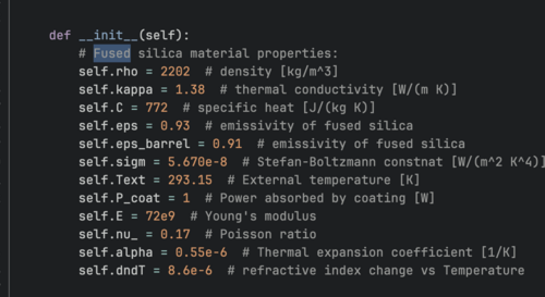
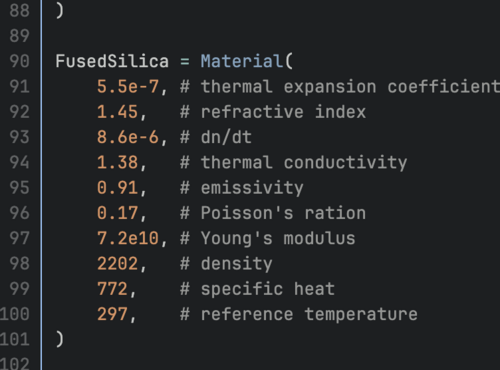
| Differences in Fused Silica parameters. |
| Attachment 1: Screenshot_2025-08-12_at_1.31.11_PM.png
|
|
| Attachment 2: Screenshot_2025-08-12_at_1.31.17_PM.png
|
|
|
633
|
Tue Aug 26 12:14:24 2025 |
Liu | Update | Interferometer Simulations | Multi-ring FROSTI design for A# with ring heater optimization |
| Multi-ring FROSTI design for A# with ring heater optimization |
| Attachment 1: Update_(1).pdf
|
.png "Update_(1).pdf")
|
|
639
|
Tue Sep 2 12:41:33 2025 |
Liu | Update | Interferometer Simulations | Multi-ring FROSTI design for A# with ring heater optimization |
| [Tyler, Liu]
Ring heater optimization, continued |
| Attachment 1: Update.pdf
|

|
|
640
|
Tue Sep 2 18:33:38 2025 |
Liu | Infrastructure | General | New lab room 1125 layout and measurement |
Action items for facilities
- Ceiling lights replacement
- Fume hood cleaned and refurbished
- Sink countertop cleaning
- Floor cleaned and waxed
-
|
| Attachment 1: 1125.pdf
|

|
|
643
|
Tue Sep 9 12:13:38 2025 |
Liu | Update | Interferometer Simulations | Multi-ring FROSTI optimization for A# with grid search |
| Multi-ring FROSTI optimization based on IFO metrics for A# with grid search |
| Attachment 1: Update.pdf
|

|
|
645
|
Tue Sep 16 12:18:09 2025 |
Liu | Update | Interferometer Simulations | Grid search optimization for single-ring FROSTI |
| Grid search optimization for single-ring FROSTI |
| Attachment 1: Update.pdf
|

|
|
647
|
Tue Sep 23 12:39:29 2025 |
Liu | Update | Interferometer Simulations | Multi-ring FROSTI optimization for A# |
|
| Attachment 1: Update.pdf
|

|
|
649
|
Tue Sep 30 12:26:15 2025 |
Liu | Update | Interferometer Simulations | FROSTI optimization for A# |
|
| Attachment 1: Update.pdf
|

|
|
652
|
Thu Oct 9 12:18:14 2025 |
Liu | Update | Interferometer Simulations | Multi-ring FROSTI optimization for A# |
|
| Attachment 1: Update.pdf
|

|
|
654
|
Thu Oct 16 10:31:20 2025 |
Liu | Update | Interferometer Simulations | Multi-ring FROSTI optimization for A# |
| Two-ring FROSTI grid search with 4D parameter space search and visualization |
| Attachment 1: interactive_plot_dropdown.html
|
| Attachment 2: Update.pdf
|

|
|
655
|
Thu Oct 23 10:07:51 2025 |
Liu | Update | Interferometer Simulations | Multi-ring FROSTI optimization for A# |
| 4D parameter space visualization and dimensionality reduction for better optimization |
| Attachment 1: loss_embedding.html
|
| Attachment 2: Update.pdf
|

|
|
658
|
Thu Oct 30 11:45:44 2025 |
Liu | Update | Interferometer Simulations | Multi-ring FROSTI optimization for A# |
| Multi-ring FROSTI optimization for A#: dimensionality reduction with PCA vs. t-SNE |
| Attachment 1: Update.pdf
|

|
|
91
|
Wed May 3 19:03:47 2023 |
Julian,Pamella and Cao | Physics | VAC | Modify vacuum asssembly and install RGA |
[Pamella, Julian, Cao]
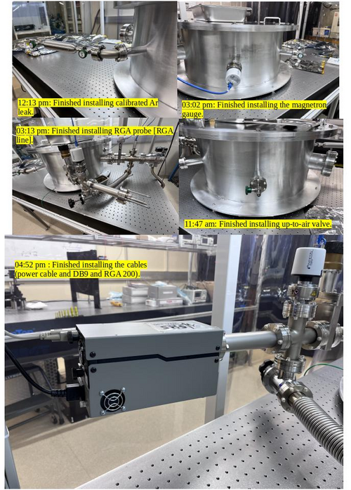
Today we started re-configuring the vacuum chamber components.
Particle count
- 10:45 am : Starting the particle count in the clean room.
- 11:13 am : Finished the particle count in the clean room.
- Zone 3 :
- 0.3 u: 2535
- 0.5 u: 1413
- 1.0 u: 789
- Zone 4 :
- 0.3 u: 457
- 0.5 u: 290
- 1.0 u: 207
Starting the reconfiguration.
- 11:21 am: Started removing up-to-air valve
- 11:30 am: Finished removing up-to-air valve.
- 11:33 am: Started removing calibrated Ar Leak and the elbow.
- 11:35 am: Finished removing calibrated Ar Leak and started assembling the up-to-air valve.
- 11:47 am: Finished assembling up-to-air valve.
- 11:48 am: Started removing magnetron gauge.
- 11:55 am: Finished removing magnetron gauge.
- 11:57 am: Started installing the elbow and calibrated Ar Leak and started removing the RGA probe
- 12:13 pm: Finished installing the elbow and calibrated Ar Leak.
- 12:20 pm: Break for lunch.
- 01:25 pm: Come back from lunch break.
- 01:30 pm: Started removing RGA line.
- 01:39 pm: Finished removing RGA line.
- 01:39 pm: Started removing gate valve [RGA line] and finished removing gate valve.
- 02:00 pm: Started installing gate valve in the new position.
- 02:08 pm: Fished installing gate valve [RGA line].
- 02:09 pm: Checked the screws in the elbow to gate valve. [RGA line].
- 02:28 pm: Finished checking the screws in the elbow to gate valve [RGA line].
- 02:29 pm: Started installing RGA line.
- 02:39 pm: Finished installing RGA line.
- 02:50 pm: Started installing magnetron gauge.(In this part we assembled gauge with the used gasket)
- 03:02 pm: Finished installing magnetron gauge.
- 03:04 pm: Started installing RGA probe [RGA line].
- 03:13 pm: Finished installing RGA probe [RGA line].
- 03:15 pm: Connected the cables to the magnetron gauge.
- 03:20 pm: Started the testing in the vacuum chamber.
- 04:30 pm: Started installing the RGA 200 and connected the cables (power cable and DB9 cable).
- 04:52 pm: Finished installing the RGA 200 and connected the cables (power cable and DB9 cable).
- 04:53 pm: Started testing the RGA connections. Logrus is able to recognize and connect to RGA unit. We are leaving the turbo pump on for a few hours before checking back for pressure readouts.
- 05:00 pm : Starting the particle count in the clean room.
- Zone 3 :
- 0.3 u: 2244
- 0.5 u: 997
- 1.0 u: 207
- Zone 4 :
- 0.3 u: 2993
- 0.5 u: 1579
- 1.0 u: 498
- 05:30 pm : Finished the particle count in the clean room.
- 05:34 pm: Test pressure readout from the gauges.
- Channel 1 : 1.06E-5 mbar
- Channel 2 :8.89E-6 mbar
- Channel 3 :5.0E-4 mbar
- 05:59 pm: Test pressure readout from the gauges.
- Channel 1: 9.09E-6 mbar
- Channel 2: 7.75E-6 mbar
- Channel 3: 5.0E-4 mbar
|
| Attachment 1: vaccum_chamber_re-configuration.jpg
|
|
|
18
|
Fri Jan 27 18:44:31 2023 |
Julian | Update | General | Vacuum Chanmber Cleaning |
| I used the IPA wipes to wipe down the inside of the chamber the best I could. I cleaned the main chamber but not any of the connecting joints. When I finished I did a once over with a fresh wipe and found no residue. |
|
15
|
Wed Jan 18 22:06:05 2023 |
Julian | Update | ELOG | Cleanroom Update |
| I wiped down all the inner walls of the cleanroom using alcohol wipes, as per Cao's instruction. |
|
22
|
Mon Feb 6 20:02:32 2023 |
Julian | Update | General | Cleanroom Update |
| I wiped down the main table (including frame, legs, and transparent shelf) and workbench using alcohol wipes. Once I cleaned all of the surfaces, I used the Hepa vacuum to pick up any fallen debris. |
|
27
|
Sat Feb 11 00:17:27 2023 |
Julian | Update | General | Vacuum Chamber Cleaning |
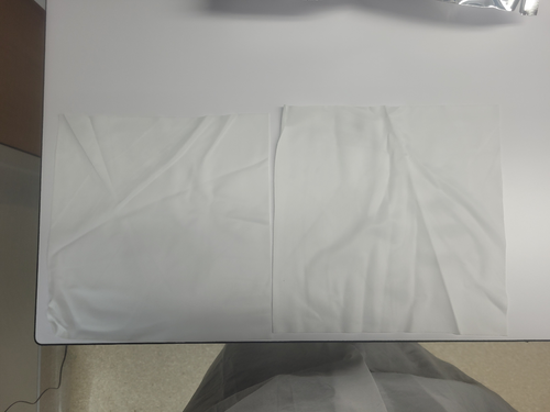
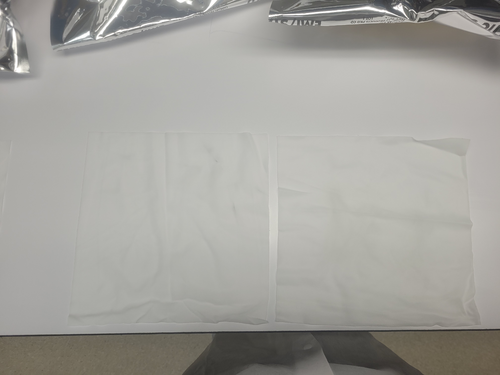
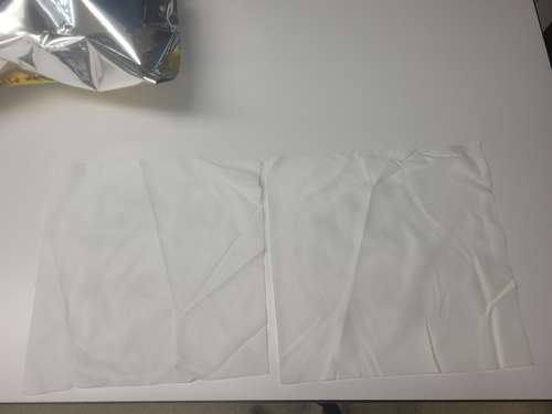
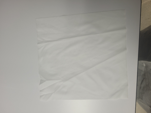
| Today I finished wiping down the rest of the vacuum chamber, specifically focusing on the connecting ports and outside surface of the chamber. When I was finished, I test wiped every surface of the chamber and took pictures confirming the current state of cleanliness; Attachment 1 "Wipes for top and bottom of chamber's upper lip." Attachment 2 " Top and bottom of chamber's lower lip." Attachment 3 "Inside and Outside main chamber." Attachment 4 "Inside connecting ports." |
| Attachment 1: 20230210_181404.jpg
|
|
| Attachment 2: 20230210_181424.jpg
|
|
| Attachment 3: 20230210_181541.jpg
|
|
| Attachment 4: 20230210_181606.jpg
|
|
|
33
|
Thu Feb 23 21:12:33 2023 |
Julian | Update | General | Vacuum Chamber Cleaning |
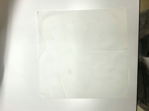
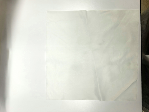
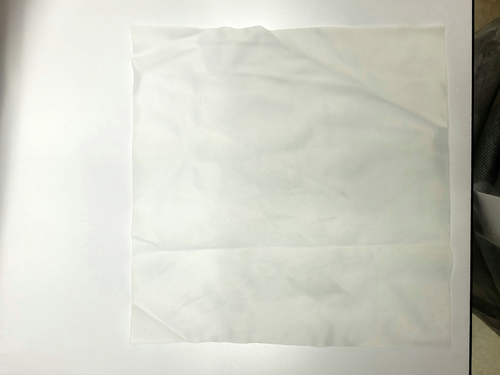
| Today I was able to come in and wipe down both sides of the vacuum chamber lid using the regular alcohol wipes and also wipes that were left to dry in the fume hood then saturated with acetone. I managed to get a good amount of the residue off both the inside and outside surfaces of the lid, then did a test wipe of both sides using acetone-soaked wipes; pictures of the wipes are attached below. Once I finished with the lid, I used another acetone wipe to test wipe the inside of the vacuum chamber. The inside is still giving off residue, but very minimally, a photo for this is attached as well. |
| Attachment 1: ChamberLid_inside.jpg
|
|
| Attachment 2: ChamberLid_outside.jpg
|
|
| Attachment 3: VacuumChamber_inside.jpg
|
|
|
41
|
Thu Mar 2 20:53:56 2023 |
Julian | Update | General | Cleanroom Update |
| Today Pamella and Julian began the final cleaning of the cleanroom, starting with the HEPA vacuuming and mopping then wiping down every surface of the laser table. We wiped the main tabletop as well as the legs, but we were unable to completely wipe down the upper frame of the table before we had to leave. For next steps, Julian will come in on Friday and finish cleaning the frame, then both of us will come in on Monday to finish the final cleaning. |
|
43
|
Sat Mar 4 00:34:46 2023 |
Julian | Update | General | Cleanroom Update |
| Today I was able to finish cleaning the frame of the laser table, and for good measure I wiped down the tabletop and exterior of the vacuum chamber when I was finished. I was also able to go through and wipe down the bags containing the vacuum parts as well as the tabletop of the workbench. |
|
55
|
Thu Mar 23 18:40:08 2023 |
Julian | Update | General | Cleanroom Update |
| Today Pamella and I came in to Hepa vacuum and mop the floor of the cleanroom for general maintenance. |
|
726
|
Thu Jul 2 13:27:48 2026 |
Joshua Marmor | Update | General | HBT SURF Update #1 |
| Update on the progress for the HBT measurement. |
| Attachment 1: group-meeting-july-2.pdf
|

|
|
731
|
Thu Jul 9 12:27:20 2026 |
Joshua Marmor | Update | General | Week 2 HBT Surf Project |
| Slides for group meeting, updates on HBT measurement |
| Attachment 1: group-meeting-july-9.pdf
|

|
|
735
|
Wed Jul 15 21:53:32 2026 |
Joshua | Infrastructure | Cleanroom | Cleanroom cleaning |
[Joshua, Mary, Ma]
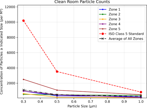
On Wednesday (7/15), a particle count measurement was performed in the clean room in all five zones.
Particle Count Measurements:
- Zone 1:
- 0.3 µm: 958
- 0.5 µm: 333
- 1.0 µm: 240
- Zone 2:
- 0.3 µm: 541
- 0.5 µm: 458
- 1.0 µm: 416
- Zone 3:
- 0.3 µm: 624
- 0.5 µm: 166
- 1.0 µm: 83
- Zone 4:
- 0.3 µm: 958
- 0.5 µm: 458
- 1.0 µm: 124
- Zone 5:
- 0.3 µm: 2499
- 0.5 µm: 1082
- 1.0 µm: 499
|
| Attachment 1: 2026-07-20_11-22-54_cleanroom_chart.png
|
|
|
736
|
Thu Jul 16 10:29:19 2026 |
Joshua | Update | General | HBT SURF Update #3 |
[Joshua, Mary, Ma, Abhi]
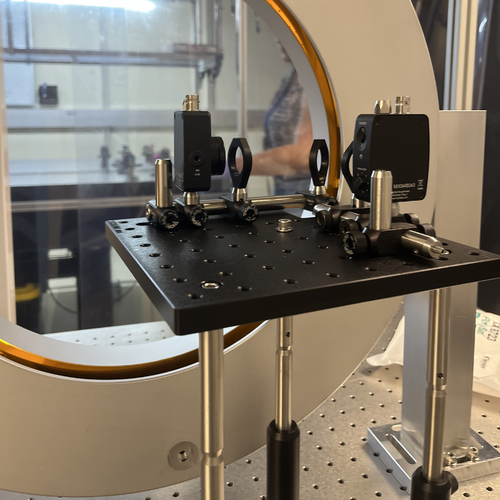
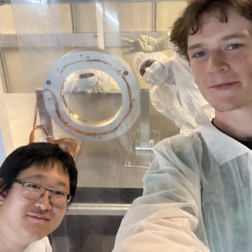
On Wednesday (7/15), the particle count measurement was sufficient, so the FROSTI was transferred into the cleanroom. We unmounted it from the plastic base, and secured it to the optical table. We also transferred the neccessary parts for the HBT setup and began assembly. The breadboard was built first (except for the lenses/beamsplitter) and mounted the the optical posts which will hold it. We placed the beamsplitter as close as possible to FROSTI without touching, and secured the feet.
It is ready for the lenses/beamsplitter to be cleaned and placed in their mounts. Then we will align the setup for maximum power on the transmissive arm.
|
| Attachment 1: IMG_8060.jpg
|
|
| Attachment 2: IMG_8057.jpg
|
|
|
737
|
Thu Jul 16 10:52:02 2026 |
Joshua | Update | General | HBT SURF Update #3 - group meeting slides |
|
| Attachment 1: group-meeting-july-16.pdf
|

|
|
739
|
Tue Jul 21 15:47:55 2026 |
Joshua | Update | General | HBT SURF Update #4 - Alignment & First Measurement |
|
HBT Alignment & First Measurement
HBT setup was aligned for maximum power on the transmissive arm, then the beamsplitter was tilted to equalize the power in each arm. Then, we set the board at
Total power: 0.156 V
Power on each photodetector: 0.078 V
We left the FROSTI on and will collect data overnight. If we need more power, we can cut the breadboard notch further.
[Joshua, Mary]
|
|
743
|
Thu Jul 30 14:15:52 2026 |
Joshua | Update | General | HBT SURF Update #5 - Group Meeting Slides |
| Attached are my group meeting slides and some calculations from Mary which predict the photon bunching cross correlation signal. |
| Attachment 1: group-meeting-slides-july-30.pdf
|

|
| Attachment 2: HBT_V2.pdf
|

|
|
746
|
Thu Aug 6 14:39:47 2026 |
Joshua | Update | General | Heating Element Power Data |
This is a measurement done to determine which heating elements output the most power. FROSTI was supplied 33V, and a photodetector was held to the center of each heating element directly at the aperture.
Element #1 (top), RTD0 - 0.33 V
Element #2 (bottom right), RTD1 - 0.21 V
Element #3 (top left), RTD2 - 0.15 V
Element #4 (bottom), RTD3 - 0.33 V
Element #5 (bottom left), RTD4 - 0.31 V
Element #6 (right), RTD5 - 0.25 V
Element #7 (top right), RTD6 - 0.00 V (shorted)
Element #8 (left), RTD7 - 0.31
|
|
90
|
Tue May 2 17:03:14 2023 |
Jon, Cao | Physics | VAC | First pump-down test of vacuum chamber |
[Jon, Cao]
1. Re-routing of cables
We re-routed the connections between the turbo pump and its fan to the controller. Instead of going through the side of the server rack, they are now routed along the the cable tray and came down from the top of the server rack.
2. Planning for vacuum assembly re-configuration
While preparing for our first pump-down, we notices that RGA pump line gate valve, at its fully closed position, is higher than the height of the chamber lid. The full range gauge attached to the RGA line, while not that high, can also cause obstruction during removal/ installation of the vacuum lid. The calibrated leak, eventhough is now running within the perimeter of the optical table, it stills introduce weak points that are susceptible to damage if personnel installing chamber lid may lean onto it. Thus we made a few suggested modification to the vacuum chamber assembly:
- Move the entire RGA arm to the mirrored CF port, where the Up-to-Air valve is at
- Move the Up-to-Air valve to the calibrated leak port
- Move the calibrated Ar leak the main chamber full-range gauge port
- Move the full-range gauge to the RGA line port
3. First test pump-down
- With all valves closed, we started scroll pump, pump line quickly got down to 6.08 mbar from atmospheric 1000 mbar (measured by Pirani gauge, channel 3 on controller )
- We open Lesker angled valve and let the RGA arm pumped down, Pirani gauge read 6.3 mbar while the full-range guage on RGA line reads 4.9 mbar ( channel 1 on controller )
- We open the pump line gate to expose the pump to the main volume, all gaugues readout immediate rise back up 1000 mbar. After 3 minutes, we started to see channel 3 slowly dropped down. A minute later channel 1 and 2 (main body) also dropped down. The slow pressure dropping speed and 6.3 mbar measured earlier got us suspected that there is some large leaks
- We proceed to tighten all the ports as the vacuum is pumped down. In particular, we found that large feedthrough port still required a lot of tightening up
- As we tighten up all the ports, after 40 minutes, the gauges are now
- Channel 1 : RGA line full-range gauge: 2.55E-1 mbar
- Channel 2 : Main chamber full-range gauge: 2.60E-1 mbar
- Channel 3 : Pump line Pirani gauge: 2.94E-1 mbar
Compare this to the scroll pump manual , Table 1, page 3, the ultimate pressure of the scroll pump is 2.5E-1 Torr (3.3E-1 mbar), we thus managed to achieve scroll pump ultimate pressure
- Turn on turbo pump : Change turbo pump controller from REMOTE to FRONT PANEL mode by pressing both "COUNTERS" and "MEASURE" buttons at the same time, select "MODE=FRONT"
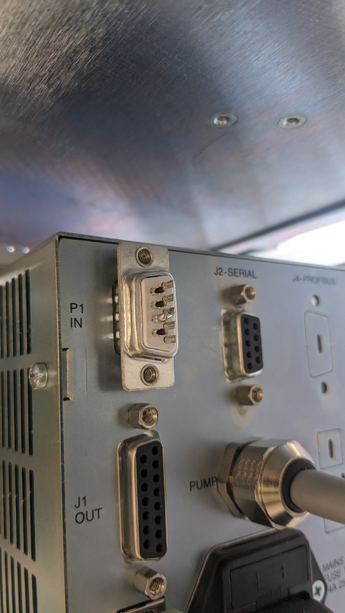
- Shorting interlock pin: since we do not have an interlock signal for the controller, use the provided DB-9 connector that has pin 3 and 8 shorted and connect this to the P1 IN connection at the rear of the controller (see attachment 1 )
- Press "START" on the controller to start the turbo pump
- The pressure readout from the gauges quickly dropped down. After 3 minutes, the Pirani range is maxed out at 0.5E-3 mbar. After 20 minutes, we recorded the following values:
- Channel 1 : RGA line full-range gauge: 1.50E-5 mbar
- Channel 2 : Main chamber full-range gauge: 1.89E-5 mbar
- Channel 3 : Pump line Pirani gauge: 5.0E-4 mbar
This is Medium vacuum , we want to further reduce this by 2 orders of magnitude. However, we can run RGA test + helium leak test at this pressure
- Turn off turbo pump, wait for 10 minutes, turn off scroll pump, open Up-to-Air valve, all pressure gauges indicated pressure returned back to atmospheric pressure
3. To-do actions
- Run RGA test to get information about contamination status of vacuum
- Implement suggested changes in section 2
- Check and modify suspected poor connection: Pirani gauge on pump line. A gap can be seen between connection. There's no good way to tighten it with the screw. Maybe use threaded pin + hex bolt?
- Controller communications
|
| Attachment 1: PXL_20230502_203343616.jpg
|
|
| Attachment 2: PXL_20230502_210234897.MP.jpg
|
|
|
138
|
Thu Jun 29 18:27:26 2023 |
Jon, Cao | Infrastructure | VAC | Vacuum bake attempt 3: success! |
| [Jon, Cao]
Summary : We resolved problems with heaters tripping power and were able to proceed with chamber baking
1. Circuit connection adjustment
After yesterday elog 137, today we resolved most of these issues. After Jon contacted Facilities, the LP3B 6 circuit was reset and the cleanroom filter & light panels resumed to work as normal.
Regarding the connection of the heaters. we made the following adjustments:
- High-temperature controller powering lid + upper volume heater: connect to LP3B 8 circuit (clean room sides, 2 outlets)
- High-temperature controller powering bottom + lower volume heater : connect to LP3B 4 circuit (workstation side, 2 outlets)
2. Replacement of vacuum nipple insulation
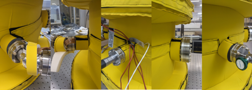
We had also received new insulation pieces from Worbo today to replace the existing insulation with the new ones (see images). These cover the 2 4" tubes (for 6" flanges ) and the 4 1.5" tubes (for 2.75" flanges). The new insulations fit perfectly on these tubes.
I also placed all insulation taken off from the last elog back onto the chamber ( these are insulations for the pumps and RGA lines).
3. Baking
We started ramping up chamber temperature at 1:41 pm over the course of two hours:
- Starting set point: 40 deg C
- Step increase: 10 deg C up to 80 deg C, 5 deg C from 80 deg to 120 deg C
- At each step, the temperature readouts show approx. 2.1 deg C overshooting, wait to settle back to approx 1.5 deg C overshoot before increase the set point again
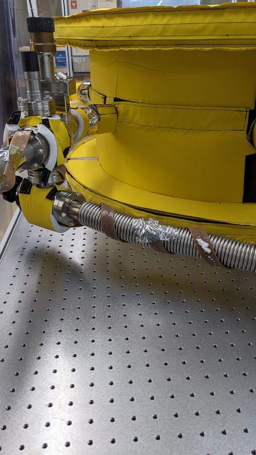
We noticed some smoke emanating from flexible bypass line insulation but none from other locations that were previously smoking . We think this is because the high winding density around the bypass line for such a small volume. Adjustment for next bake: Change the location of PID controller RTD to the bypass line . For now, we remove the insulation around bypass to prevent insulation overheating and encourage convection cooling (see image)
The temperature of the chamber reached as stable 120 deg C without any power issues at 3:45 pm. I waited another 15 minutes to verify its stability and the official baking duration started at 4:00 pm Jun 29 2023. Since we are baking at 120 deg C instead of the standard 150 deg C for Aluminium, the duration for the bake will be over three days until Monday morning, upon which we will slowly ramp down the the temperature.
|
| Attachment 1: NewInsulation.png
|
|
| Attachment 2: BypassLineInsulation.jpg
|
|