ID |
Date |
Author |
Type |
Category |
Subject |
123
|
Tue Jun 13 21:33:46 2023 |
Pamella | Update | General | New cabinet for PPI |
[Pamella and Dr.Richardson]
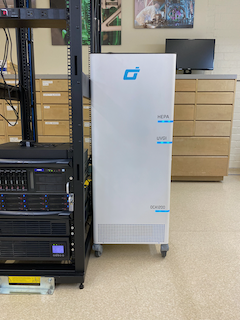
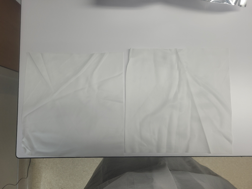
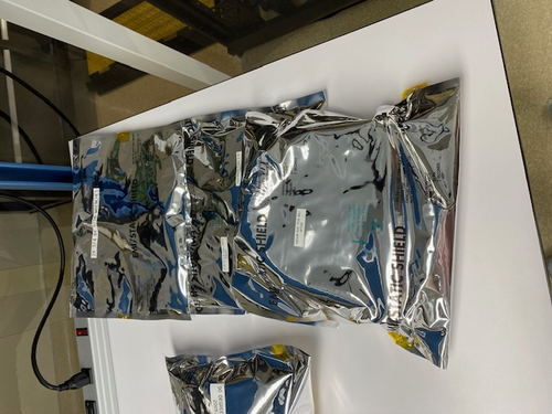
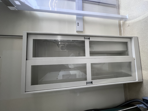
Dr. Richardson installed the new cabinet outside the room for the PPI equipments, and then I wiped all surfaces inside and outside of the new cabinet.
Dr.Richardson and I have finished organizing the PPI within the new cabinet. Also we have new supplies of gloves, and will likely have more supplies for other PPIs soon. |
154
|
Thu Jul 13 15:31:21 2023 |
Jon | Update | General | Ant traps placed around lab |
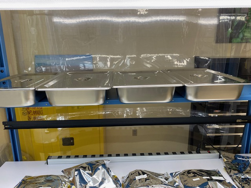
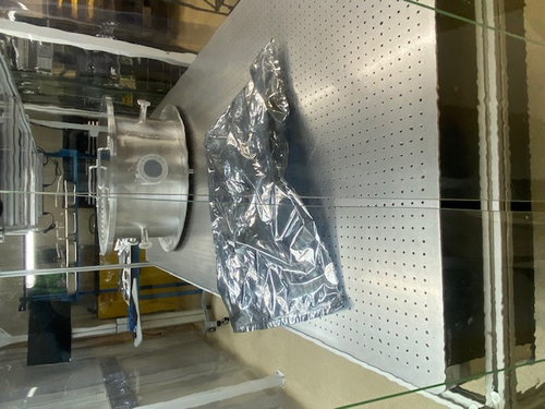
In response to reports that ants have been observed in the lab, I placed five ant bait traps around the room today. Each is sitting on the floor on top of a piece of aluminum foil, in areas unlikely to be inadvertently stepped on. They contain liquid which will spill out if picked up, so please take care not to disturb them. |
155
|
Thu Jul 13 16:59:03 2023 |
Jon | Update | General | Ant traps placed around lab |
Update: After seeing the strong response to the first set, I redistributed them to the hottest spots and added one more trap.
Quote: |
In response to reports that ants have been observed in the lab, I placed five ant bait traps around the room today. Each is sitting on the floor on top of a piece of aluminum foil, in areas unlikely to be inadvertently stepped on. They contain liquid which will spill out if picked up, so please take care not to disturb them.
|
|
158
|
Sun Jul 16 15:21:56 2023 |
Pamella | Update | General | General update about some problems in the lab. |
[Pamella]
General information about the lab facility.
- Changed sticky floor mats, because close to entrance the cleanroom, both sticky floor had a many died ants on top.
- The light on top of the internet cable bridge is burned out.. I just saw this today but I am not sure if was like this before.
- The ant bait traps seem very efficient and right now only a few ants are running around in the lab, most are dead in the bait traps, so probably in a day or two we can change those bait traps.
|
Attachment 1: IMG_8637.jpg
|
|
Attachment 2: IMG_8633.jpg
|
|
Attachment 3: IMG_8631.jpg
|
|
198
|
Wed Aug 9 11:32:56 2023 |
Jon | Infrastructure | General | New power cables |
I delivered new NEMA 5-15 (120V / 15 A) power cables to the lab for the following items:
- WS2 (cleanroom) cart - 10ft cable
- Electronics workbench overhead LED - 10ft cable
- Both PI heater controller sets - (2) 6ft cables
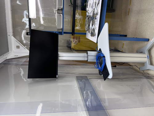
I installed the new cables on the WS2 cart and the workbench myself, and left the two 6ft cables (as pictured below) for Aiden to install on the PID controllers after the current bake is finished. |
Attachment 1: IMG_0299.jpg
|
|
217
|
Tue Aug 29 22:07:38 2023 |
Aiden | Update | General | Electronic Bench |
Dr Richardson is working on mounting more power supplies in the server rack and is using the electronics bench. Be aware to not move anything on the bench itself. |
Attachment 1: IMG_4632.jpg
|
|
220
|
Tue Sep 5 16:43:19 2023 |
Aiden | Update | General | VAC System Heating Update |
Checked on bake 5 today after 3 days of equilibrium. The RGA cross is at 106 C and the turbo pump cross is at 74 C. This was reached while the PID controllers were at 140 C. I will now slowly raise the temperature to 150 on the PID controllers and see if the difference in the RGA cross can be reduced. |
257
|
Wed Nov 8 17:55:49 2023 |
Jon | Update | General | Lab Clean-Up Day 1 |
[Jon, Tyler, Shane, Peter, Luis]
Today we completed the first phase of lab clean-up. Activities included:
- CF/KF parts stored under the cleanroom table were removed and transferred to Physics 1129
- Cleanroom workbench cleared, with all FROSTI hardware collected into one of the large SS bins
- High surfaces outside the cleanroom (lights, table enclosure frames, rack, cabinets) wiped down with IPA wipes
- Floor HEPA-vacuumed outside the cleanroom
- Sticky mats changed throughout the lab
Tomorrow, we will complete turn-over of the cleanroom (HEPA vacuuming of floors, mopping of floors, IPA wiping of softwalls and work surfaces). Shane will post a forthcoming measurement of the cleanroom particulate levels, post-turnover. |
275
|
Tue Nov 21 22:09:44 2023 |
Aiden | Update | General | Testing Parts |
[Aiden, Luis]
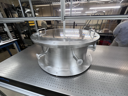
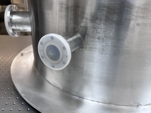
Luis and Aiden vented the chamber today. We closed off the RGA section and then proceeded to open the the vent on the main body after turning off the turbo and backing pump. We then opened the lid and placed in all the stainless steel hardware that will be used in evaluating the FROSTI optics and heater elements. We also inspected the weldments before closing it up. Check the clean and bake data base where there is now a new section outlining the parts in each test. We then closed the lid, tightened the bolts, turned the backing pump back on and let the pressure drop until it was below 1e-1 torr. Then turned the turbo pump back on and after a few hours the pressure was back down to 4.16e-7 torr. The RGA was turned off during all of this and was turned back on when done even though we closed both valves to keep the RGA volume under vacuum. |
Attachment 1: IMG_4817.jpg
|
|
Attachment 2: IMG_4815.jpg
|
|
Attachment 3: IMG_4816.jpg
|
|
Attachment 4: IMG_4814.jpg
|
|
Attachment 5: IMG_4813.jpg
|
|
Attachment 6: IMG_4812.jpg
|
|
Attachment 7: IMG_4810.jpg
|
|
Attachment 8: IMG_4811.jpg
|
|
289
|
Sat Dec 9 12:34:12 2023 |
Jon | Update | General | Electronics workshop migrated to 1129 |
[Jon, Tyler, Shane, Luis]
On Wednesday we completed the migration of the electronics workshop from 1119 to the large new workbenches in 1129. The two workstations pictured closest to the front of the room are for electronics assembly and testing, while the two in the rear will house LIGO CDS workstations. We moved all of the tools, cabling, and soldering and test equipment from 1119 to this new location. We also moved the large tool chest to 1129, as pictured, and moved the smaller tool chest to 1119 in its place.
The electronics workbench is ready for use. |
Attachment 1: IMG_0765.jpg
|
|
Attachment 2: IMG_0767.jpeg
|
|
299
|
Mon Jan 8 20:24:53 2024 |
Aiden | Update | General | |
[Jon, Aiden]
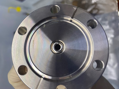
Installed the heater elements into their fixture and prepped the cables by twisting the wires into pairs. We also installed the pins onto the wires and placed them into the peek DB 25 connector. The installation tool we had did not fit the pin size we had so the pins needed to be installed by hand by opening the connector and holding them in place. In the future we will need to make sure we twist the wires together, group them, and then splice them all to the same size for easier installation. We then grouped all the twisted pairs into a bundle and zipped them together. On the left with two peek zip ties is the power and on the right is the RTD with one peek zip tie. This orientation remains true when looking at the feed through flange from the outside with the power port on closest to the wall.
We also installed the heater elements numbered 1-8 starting from the left in image 3. These elements have numbers as resistance data was taken before as to identify the heaters after they are in the chamber. After installing the DB 25 connectors we tested that the pins were in the right orientation by using a volt meter and testing the resistance where the cable runs into the the actual power supply. It seems that all the pins were properly installed and the resistance values all match with each one gaining about 2 Ohms from the cable itself.
Then the pump down was started. The pump was very slow and we suspected a leak but after changing the o-ring pump down was not any faster and we decided to leave it over break as it seemed to just be water outgassing from the aluminum. The chamber is now able to be RGA scanned and leak tested before the next bake as it is low enough pressure. |
Attachment 1: IMG_4888.jpg
|
|
Attachment 2: IMG_4886.jpg
|
|
Attachment 3: IMG_4887.jpg
|
|
303
|
Mon Jan 15 22:29:34 2024 |
Jon | Infrastructure | General | Cabinet installation & lab clean-up completed |
[Jon, Tyler, Aiden, Shane, Pooyan, Michael, Cynthia, Luke]
On Wednesday, we completed long list of work towards making the new lab (1129) fully operational and enabling the next phase of FROSTI testing.
Cabinet Installation
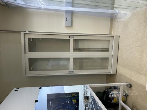
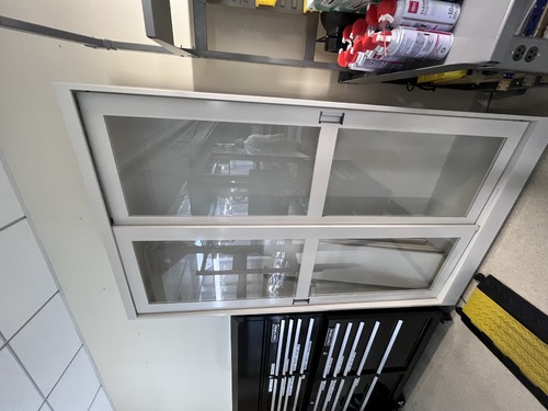
Three new VWR cabinets with sliding glass doors were installed in 1129. Each unit measures 48" (W) x 22" (D) x 84" (H) and sits along the back wall (see attachment 1). The 350-lb. cabinets were laid in place by Facilities on Monday and permanentized on Wednesday. Work included:
- Earthquake anchoring to the masonry wall
- Sliding glass doors leveled
- Shelving installed
- Wiping down of interior and exterior surfaces with IPA wipes
Server Rack Installation
A new Tripp Lite 42U open-frame rack was laid in place in 1129 and anchored to the floor (see attachment 1). This rack will house all of our general-purpose and simulation computers, which will be relocated from the 1119 rack at a later time.
Lab Clean-Up
Following installation of the new cabinets and rack, we proceeded to organize and clean both labs. Work included:
- Moved parts and equipment into permanent storage in 1129 cabinets
- Wiped down surfaces in 1119 and 1129 with polypropylene IPA wipes
- HEPA-vacuumed floors of 1119 and 1129
- Mopped floor in 1119 with Liquinox solution
- Installed new sticky mats in 1119 and 1129
- Regular cleanroom cleaning and particle counts (see 302)
- Positioned new stainless steel gowning bench outside the cleanroom (see attachment 2)
At this point, the only piece of lab equipment still to be delivered is a HEPA garment cabinet for reusing our (semi-disposable) bunny suits. It is schedule to arrive in mid-February and will sit outside the cleanroom in 1119, in the former location of the HEPA flow bench. |
Attachment 1: 1129.png
|
|
Attachment 2: 1119.png
|
|
307
|
Wed Jan 17 15:47:49 2024 |
Aiden | Update | General | Resistors for Heater Elements |
Power Res (Ohm) RTD Res (Ohm)
Heater 1= 73.6; 81.8
Heater 2= 70.4; 82.1
Heater 3= 71; 84.5
Heater 4= 71.5; 80
Heater 5= 70.5; 81.7
Heater 6= 72; 79.4
Heater 7= 69.2; 78.2
Heater 8= 71.1; 84.2 |
330
|
Tue Feb 20 08:01:30 2024 |
Jon | Infrastructure | General | Power and network equipment installed in 1129 rack |
[Jon, Tyler, Pooyan, Luis, Luke, Peter]
On Thursday we installed the power conditioning/distribution equipment and networking equipment in the new 1129 rack. The hardware is identical to the setup in the 1119 rack and includes:
- Tripp Lite SU5KRT3UTF - 208V, 5kVA on-line UPS with 120V transformer
- CyberPower PDU20M2F12R - metered power distribution unit, (14) NEMA 5-20R
- Ubiquiti USW-Pro-48 - 48 port 10Gbps network switch
The UPS is connected to a 208V NEMA 6-30R outlet in the overhead cable tray, which is on the building's "standby" (backup power) circuit. An 8-ft L6-30 extension cord has been ordered to permanently run the power cable through the cable tray.
The network switch will be connected to a Cat6 cable that was recently run by ITS from the 1119 rack, allowing the lab's LAN to be extended into 1129. This Ethernet link remains to be tested.
Quote: |
Server Rack Installation
A new Tripp Lite 42U open-frame rack was laid in place in 1129 and anchored to the floor (see attachment 1). This rack will house all of our general-purpose and simulation computers, which will be relocated from the 1119 rack at a later time.
|
|
Attachment 1: IMG_0924.jpeg
|
|
Attachment 2: IMG_0925.jpeg
|
|
Attachment 3: IMG_0921.jpeg
|
|
Attachment 4: IMG_0922.jpeg
|
|
332
|
Tue Feb 20 18:08:24 2024 |
Aiden | Update | General | Degassing the RGA |
I took an RGA measurement before and after degassing the RGA. Both data was taken with the Argon open. The pressure before taking data was 2.39 e-8 torr in the main volume. Note that the main chamber was fully valved off for the degas and the main chamber pressure quickly rose to e-6 torr. Further investigation of this rise should be done as this might be the main culprit for the leaking. |
Attachment 1: bake11_240220_Elements_postdegas_ArO.png
|
|
Attachment 2: bake11_240220_Elements_predegas_ArO.png
|
|
340
|
Mon Feb 26 15:15:39 2024 |
Aiden | Update | General | Vacuum Chamber Baking Update |
Started Bake 12 on Wednesday Feb. 21 and turned the bake off on Saturday Feb. 24. This was a normal low temp bake with the PID controllers set to 110 degC. |
344
|
Wed Feb 28 12:02:08 2024 |
Tyler | Update | General | Resistors for Heater Elements Update |
Power Res (Ohm) RTD Res (Ohm)
Heater 1= 72.8; 80.6
Heater 2= 69.5; 80.8
Heater 3= 70; 83.2
Heater 4= 70.6; 78.7
Heater 5= 69.9; 80.6
Heater 6= 71.1; 78.2
Heater 7= 68.5; 76.8
Heater 8= 70.1; 82.8
Quote: |
Power Res (Ohm) RTD Res (Ohm)
Heater 1= 73.6; 81.8
Heater 2= 70.4; 82.1
Heater 3= 71; 84.5
Heater 4= 71.5; 80
Heater 5= 70.5; 81.7
Heater 6= 72; 79.4
Heater 7= 69.2; 78.2
Heater 8= 71.1; 84.2 |
|
352
|
Sun Mar 24 11:49:27 2024 |
Aiden | Update | General | FROSTI RGA Scan |
Took RGA data 1 day after the conclusion of Bake 13. Bake 13 ended on Saturday March 23, the RGA data shown was taken on Sunday March 24. The scan shows that the FROSTI is very clean with no outgassing. The HC levels are at 25 e-10. The pressure in the chamber was also a 1.64 e-8 Torr. |
Attachment 1: bake13_240324_FROSTI_ArC.png
|
|
Attachment 2: bake13_240324_FROSTI_ArO.png
|
|
377
|
Mon Jun 17 11:47:46 2024 |
Liu | Infrastructure | General | Temporary cooling units for the labs |
Below are the temporary cooling units installed last week in labs 1119 and 1129. They are the temp. replacement for the building AC system, which will be shut down during the Physics roof replacement. |
Attachment 1: 1119.jpg
|
|
Attachment 2: 1129.jpg
|
|
402
|
Thu Jul 11 21:01:37 2024 |
Jon | Infrastructure | General | Cable tray installed in 1129 |
Today I installed a 10' cable tray in 1129, for permanently routing Ethernet lines to the workstations. It is securely bolted to C-channels in the side wall and in the center cable tray. |
Attachment 1: IMG_1395.png
|
|
Attachment 2: IMG_1396.png
|
|
403
|
Sat Jul 13 15:09:04 2024 |
Luke | Update | General | Ring heater COMSL model update |
After the feedback from last meeting and Liu's help narrowing down what I should do to improve the model. I made some changes: First with Liu's help I made the proportions of the test mass and ring heater much more reasonable and parametrized by constants. Second from Cao's paper "FROSTI Nonimaging Reflector Design" Liu showed me what I should do to define the elliptical mirrors. Third during Friday's modeling/programming meeting walked me through getting the different irradiance plots to work. |
Attachment 1: image_2024-07-13_150654436.png
|
|
Attachment 2: image_2024-07-13_150704735.png
|
|
Attachment 3: image_2024-07-13_150716079.png
|
|
Attachment 4: image_2024-07-13_150726593.png
|
|
418
|
Tue Jul 30 07:42:47 2024 |
Jon | Infrastructure | General | Cable tray installed in 1119 |
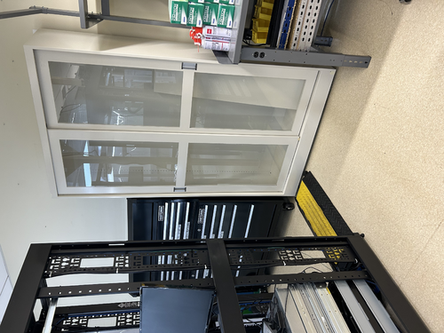
Yesterday I installed another 5' cable tray in 1119, for permanently routing Ethernet lines to the L-bench. It is securely bolted to the top of the electronics rack, on one end, and to the top of the glass-door storage cabinet, on the other. This eliminates the need for the cable ramp which previously sat behind the rack. |
Attachment 1: cable_tray_1119.jpg
|
|
471
|
Wed Nov 13 14:06:00 2024 |
Luke | Update | General | |
slides |
483
|
Mon Dec 2 13:35:45 2024 |
Luke | Update | General | Clean and bake of Viton O-rings |
[Luke, Luis]
We couldn't access the bake log on the wiki. (see attached) So we looked in the documentation provided on the DCC to find at what temperature to bake the Viton O-rings. We found that we should bake Viton at 180°C for 24 hours.
So we sonic-washed the O-rings, dried them, and then put them in the oven set to the following:
100°C in 15 minutes
100°C for 30 minutes
180°C in 30 minutes
180°C for 24 hours
30°C in 2 hours
Other things of note:
We refilled the water container as it was running out.
The nitrogen used to dry the clean and baked objects is now critically low.
The helium used in leak testing is also quite low (~400 psi).
Regarding the vacuum chamber:
I reattached the pressure gauges to the chamber and gave them about an hour to stabilize. They read out main 8.7e-9, RGA 2.6e-9. Please note these pressures should lower more as we only stopped baking on Saturday afternoon. |
Attachment 1: image_(2).png
|
|
500
|
Tue Jan 21 10:12:02 2025 |
Luke | Summary | General | Frosti toy model |
[Luke, Liu]
Over the winter break I have been working on this desmos toy model of the Frosti. There are still a few rough spots but I belive that it is a good visual representation of a 2D slice of the frosti. |
502
|
Sat Jan 25 18:19:39 2025 |
Luke | Update | General | Ringheater modeling Update |
Here is a quick update on some of the things I have been working on regarding my project. |
507
|
Sat Feb 1 17:25:52 2025 |
Luke | Summary | General | Cleanroom cleaning |
[Luke, Cece, Luis]
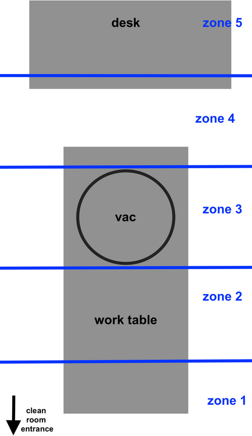
Particle Count Measurements:
- Pre-cleaning (12:15 PM):
- Zone 3:
- 0.3 µm: 1325
- 0.5 µm: 265
- 1.0 µm: 0
- Zone 4:
- 0.3 µm: 618
- 0.5 µm: 132
- 1.0 µm: 44
- Started Cleaning (3:20 pm)
- Finished Cleaning (4:20 pm)
- Post-cleaning (4:35 PM):
- Zone 3:
- 0.3 µm: 1106
- 0.5 µm: 221
- 1.0 µm: 0
- Zone 4:
- 0.3 µm: 530
- 0.5 µm: 44
- 1.0 µm: 0
|
Attachment 1: 20250131_particalcount.png
|
|
513
|
Sun Feb 16 16:45:18 2025 |
Luke | Update | General | Ringheater position optimization |
Over the last couple weeks I have been working on finding the optimal position of the ringheater's thermal profile.
Today I would like to give an update of where I am at and my next steps.
Using the python COMSOL interface I have been able to run and save deformation data sweeping through a great deal of potential combinations of widths and positions.
I then calculated their zernike coefficients and using a very simple "quality" function (02 - (40)*10 - (4-4)*10), where 02 stands for the zernike mode of quadratic deformation, I was able to generate a heat map of comparing the "quality" verses the width and position used.
Seen below are four plots. The first is simply the 02 coefficient of the decomposition followed by the negative of 40 and 4-4 then the "quality."
This 'quality' function was an arbitrary choice on my part. I believe that my next step would either be defining a more useful function or using finesse to model the actual effects of this surface deformation. |
Attachment 1: 02.png
|
|
Attachment 2: _40.png
|
|
Attachment 3: _4-4.png
|
|
Attachment 4: 02_40_4-4.png
|
|
73
|
Wed Apr 19 17:39:50 2023 |
Pamella | Update | FLIR | FLIR project |
FLIR project updates- Initial tests
- 10:00: Starting test in position 2 cm to the black wall.
- Parameters : 0,305 A, 05,5 V and the temperature inside the mirrors 141,8°C.
- 10:23 Finished this first tried and take snap. The image is attached below.
- The name for the picture for this tried is “AcquisitionImage(Apr-19-2023_10 23)”.
- 10:37. Starting test in another position now 3 cm distance to the black wall ( this is more close than the original position.)
- Parameters : 0,348 A, 05,5 V and the temperature inside the mirrors 160,3°C.
- 10:57 Finished this second tried and take a snap. The image is attached below.
- The name for the picture for this tried is “AcquisitionImage(Apr-19-2023_10 57)”.
- 11:03 Starting test another position 1.3 cm distance to black wall.
- Parameters : 0,347 A, 05,5 V and the temperature inside the mirrors 158,7°C.
- 11:18 Finished this second tried and take a snap. The image is attached below.
- The name for the picture for this tried is “AcquisitionImage(Apr-19-2023_11 18)”.
The next step should be fix the problem with the shape (aluminum foil lid).
|
Attachment 1: AcquisitionImage(Apr-19-2023_10_23)(1).jpg
|
|
Attachment 2: AcquisitionImage(Apr-19-2023_10_57)_(1).jpg
|
|
Attachment 3: AcquisitionImage(Apr-19-2023_11_18)_(2).jpg
|
|
75
|
Fri Apr 21 15:21:18 2023 |
Pamella | Update | FLIR | |
FLIR project updates
- 01:50 pm: Starting test position 34 mm distance to black wall.
- Parameters : 0.100 A, 1.5 V and the temperature inside the mirrors 40°C.
- 2:09 pm : Finished the test and figured out this position it is too far the black wall so now we change for more close position.
- 2:17 pm: Starting test in another position: 10 mm distance to the black wall( this measurement is between the black wall and the aluminum lid)
- 2:26 pm : Finished this second tried and take a snap. The image is attached below.
- The name for the picture for this tried is “AcquisitionImage(Apr-21-2023_14 26)”.
Note: The second tried the temperature didn't up more than 40°C for 8 minutes so I change the current for a few seconds.
I started with 0.98 A with 1.7 V and up until 0.350 A with 2.5 V, just for a few seconds and in this way the temperature up to 72°C and I get the snap.
The next step should be understand the problem with the shape and work in changes for get the triangle in the FLIR image. |
Attachment 1: AcquisitionImage(Apr-21-2023_14_26).jpg
|
|
104
|
Mon May 22 17:08:50 2023 |
Pamella | Update | FLIR | FLIR project - Installing the mask. |
[Pamella]
- The new mask for the reflector.
- 1:40 pm: Started reconfiguration on the FLIR camera project. Changed the old bridge for the new mask-bridge.
- 2:00 pm: Started figure out the best way to cutting the aluminum foil with the new mask. Unfortunately, I had been some problems for cutting the perfect shape triangles with the mask because the size inside the triangle is different (smaller) than cutter/knife, so is not able to do the cut with precious and carefully then maybe I need other tool for this job. Also I tried use the scissor, didn't work. However, just for the initial testing I worked with the not perfect triangles shape.
- 2:49 pm: Started installing/attaching the light in the mask.
- 3:21 pm: Finished installing the light in the mask-bridge.
- 3:22 pm: Started testing the current and voltage in the new mask-bridge for make sure the light cable is working well.
- 3:25 pm: Started measurement the resistance with multimeter.
- 3:29 pm: The measurement looks fine. The multimeter show us 14.1 Ω;
- 3:38 pm: Started putting the reflector( with the mask attached) in front of the black wall.
- 3:44 pm: Started roll the testing with the python code to observer the behavior with this new mask. Parameters: 0.14 A and 1.9 V.
- 4:00 pm: Started snapping. Parameters: 0.13 A and 1.9 V. Final Temperature: 42.7 C.
- 4:02 pm: Started trying again with more current. Parameters: 0.16 A and 2.2 V.
- 4:36 pm: Started snapping. Parameters: 0.16 A and 2.2 V. Final Temperature: 50.3 C.
- 4:55 pm: For now, we can't see the triangles in the snap so i need do some changes.
- To do:
- Change the FLIR camera position for the other side on the table.
- Start the test without the black wall.
- Try a better tool to cut the triangles inside the 3D-mask.
|
Attachment 1: Mask.jpg
|
|
Attachment 2: AcquisitionImage(May-22-2023_16_35).jpg
|
|
Attachment 3: AcquisitionImage(May-22-2023_16_01).jpg
|
|
105
|
Tue May 23 16:52:56 2023 |
Pamella | Update | FLIR | FLIR project - Reinstalling the mask and Reconfiguration FLIR position. |
[Pamella]
Reinstalling the mask and Reconfiguration FLIR position.
- Today i change the aluminum foil inside the 3D mask. After some tries i was able to have a better shape for the triangles.
- I reinstalled the connections (the light with the thermometer point). Also i checked for the focal point inside the reflector, looks fine.
- I did a reconfiguration for the initial tests, without the black wall. I moved the FLIR camera and the Reflector-Mask for other position on the table.
To do:
- Start the test with the power current on.
- I need figure out a better position for the light cables because in front of the mask isn't a good position for us do measurement.
|
Attachment 1: AcquisitionImage(May-23-2023_16_36).jpg
|
|
Attachment 2: Reconfiguration.jpg
|
|
106
|
Wed May 24 14:06:27 2023 |
Pamella | Update | FLIR | FLIR project - Tests |
[Pamella]
Initial tests
- 10:30 am : Started trying take some test with the new position/configuration between the 3D reflector-mask and the FLIR camera.
- 10:41 am : Started running the python code and take a snap. Parameters: 0.10 A, 1.4 V.
- 10:50 am : Started take the snap.It is possible see the triangles, this is a good thing. Negative thing: The middle/center point for the light maybe would be some problems for the future measurements. Parameters: 0.10A, 1.4 V and 41 C.
- 11:00 am : Started working to better align the entire structure. And double-check the distance between the 3D reflector-mask and the FLIR camera, following the instructions in Cassidy's Final FLIR Project Report.
- 11:10 am : Difficult point: I tried to attach the complete FLIR camera to the table, but I had a problem to secure the four screws to the table, the distance is not completely compatible with the table stand. Yesterday I just put two screws in the diagonal position, it works fine, but it's not the correct position to work.
- 12:00 am : Note: Two triangles take more long time to come back a not (low) irradiation position (east and south point).
- 2:00 pm : Started running the python code again.
- Parameters: 0.13 A 1.8 V.
- 2:30 pm: Started take snap. Parameters: 0.13 A, 1.8 V and 49.1 C
- 3:00 pm: Note: This time every triangles was able to come back a low irradiation position.
|
Attachment 1: AcquisitionImage(May-24-2023_10_50).jpg
|
|
Attachment 2: thumbnail_IMG-7146.jpg
|
|
Attachment 3: AcquisitionImage(May-24-2023_14_30).jpg
|
|
108
|
Tue May 30 14:51:27 2023 |
Pamella | Update | FLIR | New 3D mask - Bigger triangles shapes. |
[Pamella]
Change the 3D mask
- Started removing the old mask in the reflector.
- Started cutting the new aluminum lid for the new 3D mask and assembling in the 3D mask.
- Started doing the new cable connections for the light.
- Started testing the resistance in the new cable connections. The multimeter show us 14.2 Ω.
- Started attaching the mask with the light and the thermometer sensor.
- Started assembling the 3D mask in the reflector.
- Started the initial tests.
- 2:00 pm: Started testing the new mask. Parameters: 1.4 V 0.1A and 27 C
- 2:38 pm: Started taking snap. Final parameters:1.4 V 0.1A and Temperature: 39.9 C
- Started doing some adjustments in the triangles shapes for the futures tests.
|
Attachment 1: AcquisitionImage(May-30-2023_14_38).jpg
|
|
Attachment 2: thumbnail_IMG-7303.jpg
|
|
112
|
Wed May 31 16:55:55 2023 |
Pamella | Update | FLIR | FLIR- Focus distance |
[Pamella and Tyler]
- We changed the FLIR Focus Distance for around 0.55 m.
- Note: The old focus distance was 1.3 m.
- We tested this new focus distances and looks good. I attached a snap below.
Parameters: 0.1 A , 1.5 V and 38.4 C.
|
Attachment 1: AcquisitionImage(May-31-2023_16_40).jpg
|
|
Attachment 2: thumbnail_IMG_7310.jpg
|
|
113
|
Thu Jun 1 14:41:36 2023 |
Pamella | Update | FLIR | FLIR project - Test without the black wall. |
[Pamella]
Test without the black wall.
General test:.
- 11:15 am : Started running the code. Parameters: 0.11 A, 1.9V and focus distance around 0.55m.
- 11:28 am : Started snapping the screen. Parameters: 0.12 A, 1.8V and 44.1 C .
First trying:
- 01:18 pm : Started testing and collection data. Parameters: 0.09 A, 1.4V. Reference position: (0,0).
- 01:28 pm : Started snapping the screen. Parameters: 0.10 A, 1.5V and 37.9 C. Reference position: (0,0).
Second trying:
- 01:34 pm : Started testing and collection data. Parameters: 0.08 A, 1.4V. Reference position: (0,-0.10).
- 01:44 pm : Started snapping the screen. Parameters: 0.09 A, 1.7V and 35.8 C. Reference position: (0,-0.10).
Third trying:
- 01:50 pm : Started testing and collection data. Parameters: 0.08 A, 1.3V. Reference position: (0,-0.05).
- 02:00 pm : Started snapping the screen. Parameters: 0.09 A, 1.4V and 35.4 C. Reference position: (0,-0.05).
Fourth trying:
- 02:04 pm : Started testing and collection data. Parameters: 0.09 A, 1.3V. Reference position: (0,0.05).
- 02:14 pm : Started snapping the screen. Parameters: 0.11 A, 1.6V and 41.7 C. Reference position: (0,0.05).
Note: So today i tried collecting data for every possible position in Y (height) way for starting analyses and compares the triangles shapes. I realize maybe we get a problem because i keep the same time in every try but the final temperature and the parameters change every time, so i will try do a better system to keep the parameters equal, maybe i can wait the reflector be back to a normal temperature after every test or keep the system on all the time and just change the reflector position. I pretty sure this was the problem.
|
Attachment 1: thumbnail_IMG_7316.jpg
|
|
Attachment 2: AcquisitionImage(Jun-01-2023_14_14).jpg
|
|
Attachment 3: thumbnail_IMG_7320.jpg
|
|
114
|
Fri Jun 2 14:28:40 2023 |
Pamella | Update | FLIR | FLIR project - Test without the black wall. |
[Pamella]
Test without the black wall.
Note: So today i collected data for some positions in axis Y (height) for starting analyses and compares the triangles shapes. I tried keep the same parameters every time.
First position:
- 01:20 pm : Started testing and collection data. Parameters: 0.10 A, 1.6V. Reference position: (0,0.05).
- 01:30 pm : Started snapping the screen. Parameters: 0.10 A, 1.6V and 37.7 C. Reference position: (0,0.05).
Second position:
- 01:34 pm : Started testing and collection data. Parameters: 0.10 A, 1.6V Reference position: (0,0).
- 01:44 pm : Started snapping the screen. Parameters: 0.10 A, 1.6V and 40.6 C. Reference position: (0,0).
Third position:
- 01:50 pm : Started testing and collection data. Parameters: 0.10 A, 1.6V. Reference position: (0,-0.05).
- 02:00 pm : Started snapping the screen. Parameters: 0.10 A, 1.6V and 39.1C. Reference position: (0,-0.05).
Fourth position:
- 02:03 pm : Started testing and collection data. Parameters: 0.10 A, 1.6V. Reference position: (0,-0.10).
- 02:13 pm : Started snapping the screen. Parameters: 0.10 A, 1.6V and 39.6 C. Reference position: (0,-0.10).
|
Attachment 1: 1Axis_y___tests.jpg
|
|
117
|
Thu Jun 8 14:51:58 2023 |
Pamella | Update | FLIR | FLIR- Distance |
[Pamella, Tyler]
- Today we change the distance between the FLIR camera and reflector (3D-Mask with mirrors and light). Now the distance is 0.2032 m.
- Note: This distance is just for take a snap most close possible but we need move again for a little far way because in this distance we can't move up and down the reflector for have data to compare.
|
Attachment 1: AcquisitionImage(Jun-08-2023_14_33).jpg
|
|
Attachment 2: thumbnail_IMG_7441.jpg
|
|
118
|
Mon Jun 12 12:15:10 2023 |
Pamella | Update | FLIR | FLIR- Take data in the closest point. |
[Pamella]
- Used the closest point possible for the reflector in front of the FLIR camera.
- 11:32 am : Turned on the electronic device (current on) for started taking data.
- 11:50 am: Started checking the temperature and the parameters.
- 12:04 pm: Started taking snap after waited for 30 minutes with the current on. Parameters: Current: 0.13A , Volt: 1.8V and Temperature: 51.4 C.
- Note: This snap is in the most close point possible, after that I should be change the reflector position and also the optical focus distance in the FLIR camera.
We can see, in the photo attached below, thought in this closest position the cable connect to reflector is a bit problem to take a good snap also the have issues to keep very uniform triangles (temperature) in the reflector.
- To do: I'll change the position on the light inside to see if the problem it is in the focal point inside the reflector (mirror).
|
Attachment 1: AcquisitionImage(Jun-12-2023_12_04).jpg
|
|
125
|
Fri Jun 16 16:17:13 2023 |
Pamella | Update | FLIR | FLIR - Change the position |
[Pamella]
Today I change the distance between the FLIR camera and reflector (3D-Mask with mirrors and light). Now the distance is 0.3282 m.
- Note: In this distance is possible move up and down the reflector and take data to compare.
- The focal point inside the reflector keeping like little problem, every time I tried adjust this I got some triangles is not with "perfect emission" (looks like different than the others). Also if I move up or down the focal point inside the reflector have some issues as well.Therefore I am working on that.
|
Attachment 1: IMG-7637.jpg
|
|
127
|
Mon Jun 19 11:20:57 2023 |
Pamella | Update | FLIR | FLIR - Fixed some problems |
[Pamella]
- 08:59 am: Turned on the electronic device (current on) for started taking data.
- 09:37 am: Tried understanding the error in the focal point. I realized the pillars was in the wrong place and because of that we got problems to keep the reflector in the correct position to FLIR focus.
- 09:58 am: Started checking the temperature and the parameters.Changed the pillars to the original position (0.5645m) just for checking with the problem was the pillar in the wrong place.
- 10:06 am: Changed the reflector to point (0.3282m) and now in the correct position for the pillars. Started take snap and collecting data. I moved up and down the reflector for got data to compare later.
- 10:37 am: Used the closest point possible for the reflector in front of the FLIR camera with the correct spot for the pillars.(0.2032m)
- 11:00 am: Started taking snap after kept the current on for a few hours. Parameters: Current: 0.10A , Volt: 1.3V and Temperature: 41.9 C.
- I attached below the snap in the most close point possible, now i can see a better photo and I think a fixed the problem about the focal point in the reflector for have more uniformity between the triangles, isn't perfect yet but now is just some adjustments. Furthermore after that I should be change the reflector position and also the optical focus distance in the FLIR camera and try use the black wall.
|
Attachment 1: AcquisitionImage(Jun-19-2023_11_00).jpg
|
|
132
|
Fri Jun 23 15:47:06 2023 |
Pamella | Update | FLIR | Collecting data - Moving horizontal and vertical on screen. |
[Pamella]
- 02:09 pm: Turned on the device (current on)
- 02:42 pm: Started taking snap on position one (Reference point: 0,-0.062). Parameters:0.10A,1.5V,41.5C
- I took multiplier snap on the same position for compare after on data analyzes. I just wanted one/two minute break between the snaps. I did that same for every position.
- 02:55 pm: Started taking snap on position two (Reference point:-0.10,-0.062 ). Parameters: 0.10A,1.5v,43 C
- 03:01 pm: Started taking snap on position three (Reference point:0.05 ,-0.062). Parameters: 0.1A,1.4V,42.8C
- 03:07 pm: Started taking snap on position four (Reference point: 0.05,0.045). Parameters:0.10A,1.5V,43.6 C
- 03:15 pm: Started taking snap on position five (Reference point: 0,0.045). Parameters:0.10A, 1.4V, 44.1C
- 03:22 pm: Started taking snap on position six (Reference point: 0,0.045). Parameters: 0.10A,1.4V,43.3 C
- We can see in the photos attached below than have some differences between every position so I should be starting analyzes on that.
|
Attachment 1: AcquisitionImage(Jun-23-2023_14_42).jpg
|
|
Attachment 2: AcquisitionImage(Jun-23-2023_14_57).jpg
|
|
Attachment 3: AcquisitionImage(Jun-23-2023_15_01).jpg
|
|
Attachment 4: AcquisitionImage(Jun-23-2023_15_07)_(3).jpg
|
|
Attachment 5: AcquisitionImage(Jun-23-2023_15_15).jpg
|
|
Attachment 6: AcquisitionImage(Jun-23-2023_15_22).jpg
|
|
135
|
Tue Jun 27 15:18:26 2023 |
Pamella | Update | FLIR | New data collection |
Yesterday, I did a new data collection. I could get a better data in this time and I realized than I need use some angle on the reflector for got a better shot. I need do that because the FLIR camera just is able to get the triangle shape for complete if I keep exactly in same line for center point on the camera but for the data now I need move the refletor to go up and go down. So wasn't working very well if I keep the reflector without angle.
Now I am using the refletor with a angle. In the more high part I turn the mask for look the table and in the lower part I turn the mask to look up. I attached a photo below for this configuration.
Also the processes to get the data was the same than I using last time, the only diference is now I just moved the pillar after get data for high position and lower position for the same reference point on the triangle shape.
Note: In most data it is impossible to keep the same parameter for current, voltage and temperature. Most have a small variation but not a big difference. For example: I got the temperature in the first position 46.8 °C and in the second position I got 47.1 °C, it's just an example. It's just so we know that we don't have the exact same parameters all the time. In my opinion this is not a problem because it is just a small variation.
- 09:35 am: Turned on the device (current on). I wanted for 30 minutes before start get data.
- 10:05 am: Started taking snap on position one (Reference point: -0.10, 0.050). Parameters:0.11A,1.7V,46.8°C
- I took four snap on the same position for compare after on data analyzes. I just wanted one minute break between the snaps. I did the same for every position.
- 10:15 am: Started taking snap on position two (Reference point:-0.10,-0.050 ). Parameters: 0.11A,1.7V,47.1° C
- 10:22 am: Started taking snap on position three (Reference point:0.00 ,0.050). Parameters: 0.11A,1.6V,48.1°C
- 10:26 am: Started taking snap on position four (Reference point: 0.00,-0.050). Parameters:0.11A,1.6V,48 °C
- 10:32 am: Started taking snap on position five (Reference point: 0.05,-0.050). Parameters:0.11A, 1.6V, 48°C
- 10:37 am: Started taking snap on position six (Reference point: 0.05,0.050). Parameters: 0.11A,1.7V,47.6 °C
- We can see in the photos attached below every position also I am working in the analyzes.
|
Attachment 1: FLIR_data.002.jpeg
|
|
Attachment 2: FLIR_data_2.002.jpeg
|
|
139
|
Fri Jun 30 15:57:28 2023 |
Pamella | Update | FLIR | Data and python code update |
Updates: Problems with the emission intensity and python code.
- Yesterday I was working on get data from FLIR reflector but unfortunately we got some problems:
- I realized than if I move the reflector a to left or right the screen doesn't get data very well(I attached a photo below). This is a problem because our idea is have the same type of emission every part on screen. Tyler and I worked to tried fix that but don't had success.
- Dr. Richardson gave me the idea to move the FLIR camera to left or right (The same happens if I move up and down) and keep the refletor on the same position every time but unfortunately we got the same problem, the screen doesn't get data very well(I attached a photo below). Now I am working to tried fix that.
- Also I was able to work on the code to isolate the triangle shape for analyzes, I attached the image for that below.
|
Attachment 1: isolation1-2.jpg
|
|
Attachment 2: AcquisitionImage(Jun-29-2023_18_27)_(1).jpg
|
|
Attachment 3: AcquisitionImage(Jun-29-2023_18_38).jpg
|
|
Attachment 4: AcquisitionImage(Jun-29-2023_18_39).jpg
|
|
140
|
Fri Jun 30 16:43:14 2023 |
Pamella | Update | FLIR | Updates: Small moving the FLIR camera |
[Pamella]
Today, I was able to make some adjustments to the FLIR camera angle, suggested by Dr. Richardson, and we got small possible movements keeping the same pattern in the shapes of the triangles. I have attached photos below. I was able to move left and right as well as up and down and it worked in four points that I marked on the table.
The only problem is that it only worked on a part of the screen, if I try to place it farther to the right or to the left, we are back to the same problem as yesterday.
|
Attachment 1: AcquisitionImage(Jun-30-2023_16_23)_(3).jpg
|
|
Attachment 2: AcquisitionImage(Jun-30-2023_16_23)_(1)(1).jpg
|
|
Attachment 3: AcquisitionImage(Jun-30-2023_16_24).jpg
|
|
Attachment 4: AcquisitionImage(Jun-30-2023_16_22)_(1)(1).jpg
|
|
Attachment 5: AcquisitionImage(Jun-30-2023_16_22)_(1).jpg
|
|
143
|
Mon Jul 3 18:38:13 2023 |
Pamella | Update | FLIR | FLIR project |
[Pamella]
- I was able to work on the python code to do analysis on the FLIR-Reflector data.
- I could plot images of total area (Tyler help me on that) with csv file and also could have isolation area for triangles. I have attached examples below. Just for now the images are of different data, so there are some differences in the shapes.
- I'm working on getting a complete analysis code to work with the different positions of the triangles and to be able to do out the statistical analysis.
- Also we keeping have problem to get good data if when we move the camera or the reflector on horizontal or vertical position. I am working a some ideas for that.
|
Attachment 1: Region.jpg
|
|
Attachment 2: triangular_region_temperature-2.jpg
|
|
Attachment 3: heatmap.jpg
|
|
Attachment 4: isolation1-4.jpg
|
|
144
|
Tue Jul 4 15:35:38 2023 |
Pamella | Update | FLIR | FLIR - reflexion problem |
[Pamella]
I was testing all the positions we need to cover when moving the FLIR camera or the reflector. I tried to find out more about the problem so I tested the position without the mask, just with the old bridge and I got the same problems, in the middle of the screen we have a very good image but if we move we have the visualization problem and we don't see the reflection very well (intensity, emissivity) in FLIR.
For this test I used very low current (0.04 A) for keep everything safety.
I also think that problem is not in the focal point of the reflector because we can see very well in the center of the screen, but maybe it is because in the parabolic reflector the reflection in the focal point is "extremely" straight, so for you to see the reflection in this point you need keep close to the middle of the screen, to see around the reflector, at the extremes, we need to change the position for the cable or the light to "change" how the flashes of light reflect and thus achieve exactly the position on the camera. It is something like the sketch/ photo attached below. |
Attachment 1: AcquisitionImage(Jul-03-2023_14_29).jpg
|
|
Attachment 2: AcquisitionImage(Jul-03-2023_14_31).jpg
|
|
Attachment 3: AcquisitionImage(Jul-03-2023_14_49).jpg
|
|
Attachment 4: Caderno_sem_título_(26)-2.jpg
|
|
Attachment 5: parabol1.print.png
|
|
149
|
Thu Jul 6 18:03:19 2023 |
Pamella | Update | FLIR | FLIR project - New configuration |
[Pamella]
Cao suggested using the project without the reflector and mask because in this case we probably got good images around the screen. So I started this yesterday and today I started to get some data to see the stabilization position and check how the parameters fluctuated. I was looking and taking snaps for an hour and a half. I'll repeat this one more time to make sure we have enough data to do analysis.
To do: The next step is to start collecting data by moving the camera FLIR and covering all six positions on the screen (2x3). Also Aiden is on hand to help and is going to make a new 3D print bridge to have good heater support.
I attached a image for the new configuration below and a snap data. |
Attachment 1: IMG_8193.jpeg
|
|
Attachment 2: IMG_8183.jpeg
|
|
Attachment 3: AcquisitionImage(Jul-06-2023_17_18)_(1).jpg
|
|
Attachment 4: region_temperature1.jpg
|
|
151
|
Sat Jul 8 14:26:17 2023 |
Pamella | Update | FLIR | Data with the new configuration without the mask and reflector. |
[Pamella]
I started collecting data by moving the camera FLIR and covering all six positions on the screen (2x3). I was looking and taking snaps for more than one hour and a half. I'll repeat this one more time to make sure we have enough data to do analysis.
I attached snap data below. This images is processed on python code. |
Attachment 1: region2-3.jpg
|
|
Attachment 2: region3-2.jpg
|
|
Attachment 3: region4.jpg
|
|
Attachment 4: region5.jpg
|
|
Attachment 5: region6.jpg
|
|
Attachment 6: region_temperature1-2.jpg
|
|
157
|
Fri Jul 14 16:49:42 2023 |
Pamella | Update | FLIR | New bridge and calibration data |
[Pamella]
Aiden 3D printed a new bridge for the heater and I installed the new bridge yesterday.
I started collecting data to plot a calibration with the heater. I'm doing measurements with current and the thermocouple (thermometer) to compare with FLIR measurements and have a good calibration. |
Attachment 1: IMG_8606.jpeg
|
|