| ID |
Date |
Author |
Type |
Category |
Subject |
|
570
|
Tue May 6 12:25:03 2025 |
Tyler | Configuration | CDS | Cymac ADC CSD measurement |
| An initial measurement of the cymbal ADC CSD is attached below. As of now, it seems that the sensitivity limit is roughly the same as that of the Red Pitaya. |
| Attachment 1: cymac_adc_rin_v1.pdf
|

|
|
585
|
Tue Jun 3 11:50:08 2025 |
Pooyan | Update | CDS | CDS update |
There are three major issues with the lab's CDS system that should be addressed. They are ordered from the highest priority to the lowest.
- CyMAC has stopped serving the fast channels (65k Hz)
The channels are still there, and the data from the slow (16 Hz) channels is served correctly, but the fast data is not served. As a result, diagggui can not retrieve any information at the moment.
Probably the issue is the same as the version conflict between daqd and nds2-server. After installing nds2-server on CyMAC and realizing that the conflict can not be resolved, I reverted the changes so that the CyMAC could be compatible with daqd, but there is a chance that there are still version conflicts that block the fast channels.
I suspect that we have broken the MSC model when adding the new button. This could explain both the fasr-channels fault and the unexpected crashes.
UPDATE 6/5
Fixes this by rebuilding the models.
Note for the future: The c1iop and c1msc models should be rebuilt together, even if no change has been made to c1iop.
- The fast channels were not saved to the frames
Reviewing the frame files showed that the daqd was only saving the 16 Hz data in the .gwf frame files. I had missed this because I only checked the existence and the integrity of the raw frame files, but never retrieved the high-frequency data itself to check it.
- NDS2-server is installed, but does not distribute the data
I managed to install the nds2-server and its satellite programs on the Chimay, and NFS mount the frame files on it. The server successfully chaches the channel names, frame files, and the data, but fails to list the channels for distribution.
Note: CyMAC machine was strangely disconnected from the network, and required manual reboot. I couldn't find any abnormal logs that could explain what happened. |
|
590
|
Tue Jun 10 12:11:14 2025 |
Pooyan | Update | CDS | CDS update |
- The MEDM models issue was fixed. The issue was that building the c1msc model alone was not enough and we had to re-build the c1iop as well, although no changes has been made to the c1iop. Added a note in the wiki on this for future reference.
- For writing the fast channels to the frame files, our CDS system should have a GDS broadcaster. I followed this wiki page to set one, but it breaks the current daqd system. Asked about it earlier today on the CDS Mattermost channel and waiting for a response.
- Maybe I should continue the distributed scheme we have been trying for the nds2-server and let another machine on the network do this.
- Question: daqd has a feature to zero-out the bad data (NaNs), and it is currently on for our system. I don't think that it's a good idea to have this. Should I turn it off?
|
|
592
|
Wed Jun 11 16:19:37 2025 |
Pooyan | Update | CDS | CDS update |
- Fast channels recorded to .gwf frame files
- The fast channels are recorded with an extra _DQ in their names. So, in ndscope and diaggui these two channels should be addressed as
- C1:MSC-V0_OUT_DQ
- C1:MSC-V1_OUT_DQ
-
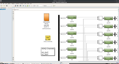
Update 6/13: enabled recording of all the ADC voltage channels so that Tyler can use all the data for the noise floor calculation. attached is an example of diagggui with almost 30 hrs of data.
|
| Attachment 1: Screenshot_20250611_154834.png
|
|
| Attachment 2: f3k.pdf
|

|
|
635
|
Tue Aug 26 12:45:41 2025 |
Christina, Ma, Tyler | Update | CDS | RIN Update |
| Slides |
|
8
|
Fri Jul 22 13:20:28 2022 |
Phoebe | Update | | Comsol |
| I will be using comsol until 1:30 pm today. I will be updating the model for the heater mount to be thicker in certain areas, so that it can feasibly be 3D printed. Specifically, the radius of the center cartridge mount has been increased to add thickness to the pipe and the arms of the bridge. This will allow us to print with a much smaller chance for error, as the printer can print objects with a minimum length of 1 mm. |
|
37
|
Tue Feb 28 19:33:51 2023 |
Peter | Update | | 532 M2 Measurements |
| Y axis of plot in units of micrometers. X axis in units of millimeters. |
|
46
|
Wed Mar 8 18:35:52 2023 |
Pamella | Update | | Lab cleaning |
| Today Pamella finished cleaning of the cleanroom, starting with the HEPA vacuuming, mopping and clearing all floor with IPA wipes.
Also Pamella and Julian finished cleaning of lab floor, starting with the HEPA vacuuming and mopping.
Shane and Pamella wiped down every surfaces of the laser table, computer table and the table with the vacuum pieces inside the cleanroom.
Shane, Peter, Tayler, Pamella and Julian then wiped down every surface of the laser table outside the cleanroom. We wiped the main tabletop as well as the legs and all parts for the table. We wiped the computer desk, the boxes, the cabinets and every part outside the cleanroom. For now we finished the lab cleaning. |
|
371
|
Fri May 31 19:37:47 2024 |
Luke | Update | | Vacuum chamber Disassembly |
| [Luke, Aiden, Jon, Michel, Tyler]
Work done:
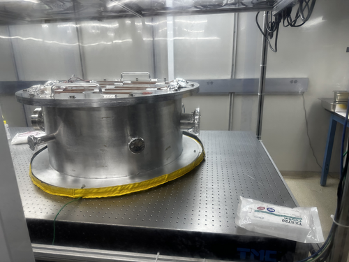
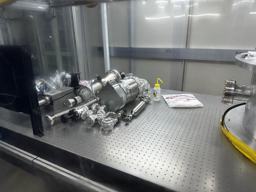
On Tuesday (5/28) we removed the RGA line with minimal difficulty. On Wednesday (5/29) we removed the turbo pump, which had a few bolts that we needed to cut. We borrowed a dremel with ceramic blades from the machine shop to help remove some of the bolts. On Thursday we moved the vacuum chamber onto the floor to check and resecure the heating band on the bottom of the vacuum chamber. We then relocated the posts the vacuum chamber rests on closer to the end of the table and reinstalled the chamber. The post’s height was also reduced from 2in to 1in.
Current state of vacuum chamber:
The vacuum chamber is currently reinstalled in its new position. Some of the parts on the table will be used in the assembly of the turbo pump and RGA lines with the others being able to be moved to storage. |
| Attachment 1: IMG_1681.jpg
|

|
| Attachment 2: IMG_1680.jpg
|

|
| Attachment 3: IMG_1680.jpg
|
|
| Attachment 4: IMG_1681.jpg
|
|
|
378
|
Wed Jun 19 18:45:14 2024 |
Luke | Update | | Vacuum chamber reassembly |
| [Luke, Aiden, Mohak , Tyler]
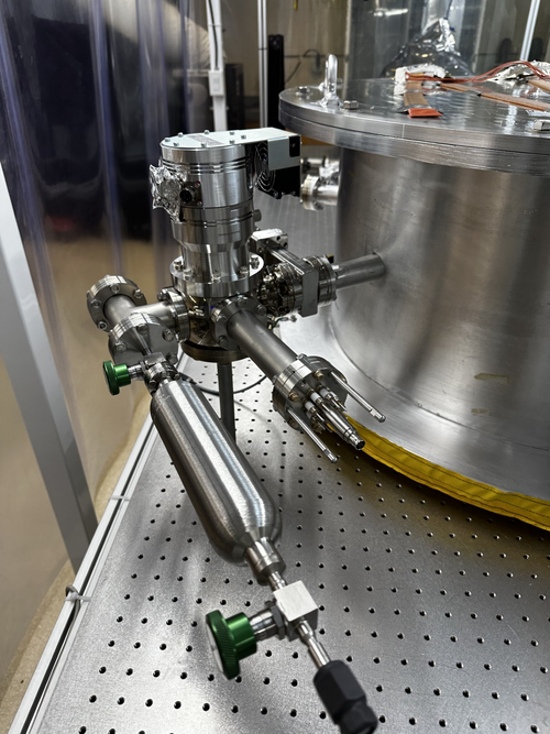
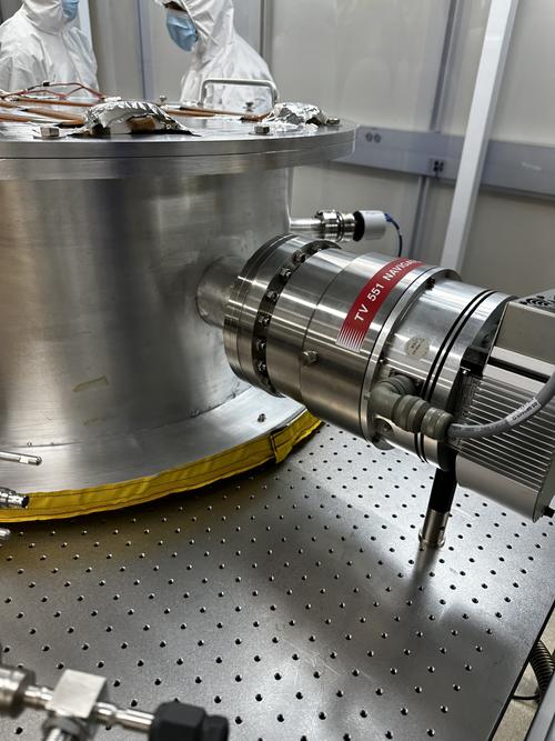
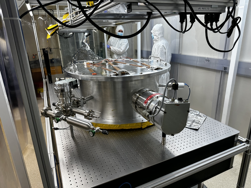
On Tuesday we had the silver screws for the spherical cube shortened by a quarter of an inch so that they would fit into the gate valve. We then attached the spherical cube to the vacuum chamber.
On Wednesday we finished assembling the RGA line and the main turbo pump. |
| Attachment 1: image_2024-06-19_182556383.png
|
|
| Attachment 2: image_2024-06-19_182631737.png
|
|
| Attachment 3: IMG_1710.jpg
|
|
|
423
|
Mon Aug 12 16:35:30 2024 |
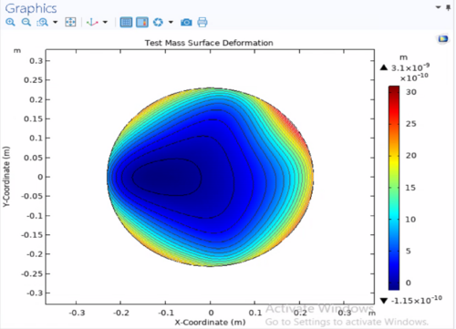
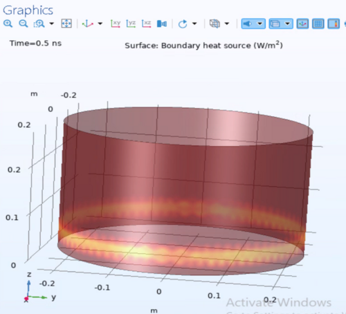
Luke | Update | | Ringheater modeling Update |
|
| Attachment 1: HR_surface_deformation.png
|
|
| Attachment 2: Irradiation_pattern_input.png
|
|
| Attachment 3: HR_surface_deformation_other.png
|
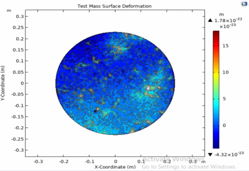
|
|
451
|
Wed Oct 2 10:31:46 2024 |
Xuesi Ma | Configuration | | Group Meeting Slides 10/2/2024 |
Group Meeting slides for Non-deterministic Heater Response.
|
| Attachment 1: Group_Meeting_10_2.pdf
|

|
|
452
|
Wed Oct 2 12:05:42 2024 |
Luke | Update | | Ringheater modeling Update |
Power point slides |
|
455
|
Wed Oct 2 14:49:59 2024 |
Liu | Update | | FROSTI ETM actuation |
| Proposed FROSTI ETM actuation on the HOM7 resonance.
Animation |
|
460
|
Wed Oct 16 14:13:31 2024 |
Liu | Update | | FROSTI with non uniform absorption scattering sources |
| Slides |
|
Draft
|
Wed Oct 23 12:33:54 2024 |
Luke | Update | | Zernike calculation update |
PowerPoint slides new
PowerPoint slides older |
|
503
|
Mon Jan 27 11:29:38 2025 |
Xuesi Ma | Update | | Heater Element Test |
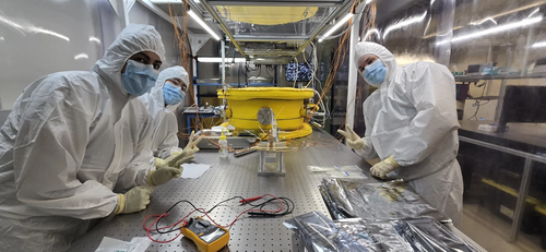
[Ma, Cece, Luke, Mary, Shane]
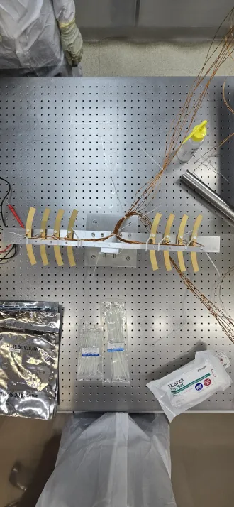
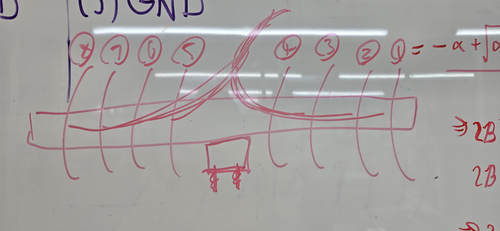
On Friday (Jan 24), we installed the heater elements on the stand. The heater elements are arranged from 1 to 8, oriented from right to left as shown in Attachment 1. Each wire has been labeled according to its corresponding element number and type (e.g., RTD connections, heater connections).
Note: We currently do not have enough PEEK zip ties, so standard zip ties have been used temporarily. These must be replaced with PEEK zip ties before the setup is placed in the vacuum chamber. |
| Attachment 1: 20250124_165434.png
|
|
| Attachment 2: 20250124_165342.png
|
|
| Attachment 3: 20250214_132811.jpg
|
|
|
504
|
Mon Jan 27 23:35:28 2025 |
Xuesi Ma | Update | | |
[Ma]
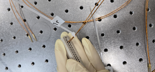
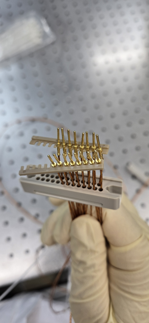
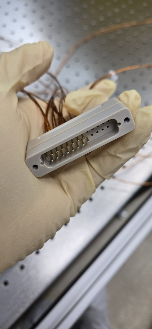
Installed all the pins to the peek DB 25 connectors |
| Attachment 1: 20250127_142647.jpg
|
|
| Attachment 2: 20250127_153454.jpg
|
|
| Attachment 3: 20250127_154516.jpg
|
|
|
506
|
Fri Jan 31 15:03:09 2025 |
Xuesi Ma | Update | | Heater Element Circuit Check |
|
[Ma] Wed 1/29/2025
No short circuit between heater element ✓
No short circuit to ground on any pin ✓
No short circuit between connectors ✓
| Heater Number |
Power Resistor before (Ohm) |
Power Resistor now (Ohm) |
RTD Resistor before (Ohm) |
RTD Resistor now (Ohm) |
| 1 |
73.6 |
73.1 |
81.8 |
81.3 |
| 2 |
70.4 |
69.6 |
82.1 |
81.6 |
| 3 |
71 |
70.5 |
84.5 |
84 |
| 4 |
71.5 |
71 |
80 |
79.4 |
| 5 |
70.5 |
70.2 |
81.7 |
81.2 |
| 6 |
72 |
71.6 |
79.4 |
78.7 |
| 7 |
69.2 |
69 |
78.2 |
77.5 |
| 8 |
71.1 |
70.6 |
84.2 |
83.6 |
|
|
508
|
Mon Feb 3 13:17:21 2025 |
Xuesi Ma | Update | | |
[Ma]
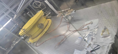
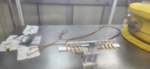
changed all zip ties to peek zip ties, and grouped wires together. The setup is ready to go into the chamber. |
| Attachment 1: 20250203_123153.jpg
|
|
| Attachment 2: 20250203_123213.jpg
|
|
|
514
|
Tue Feb 18 10:01:07 2025 |
Xuesi Ma | Update | | |
[Ma, Pooyan, Tyler]
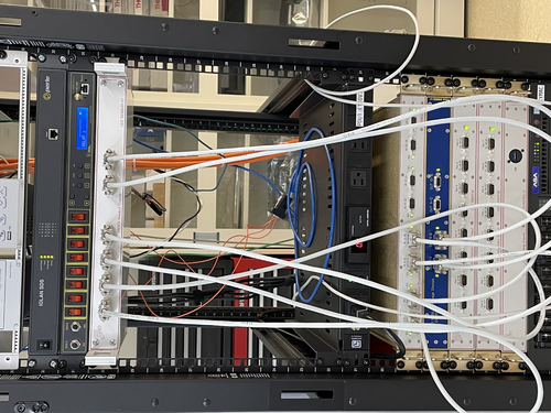
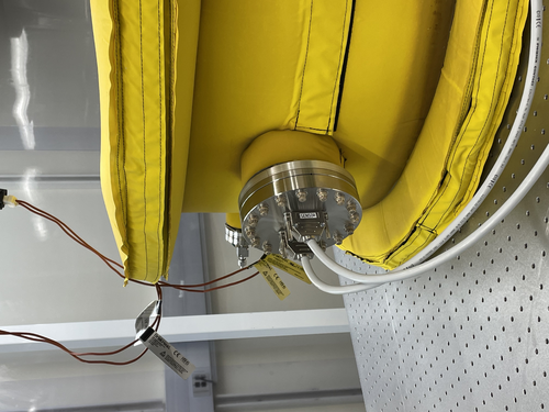
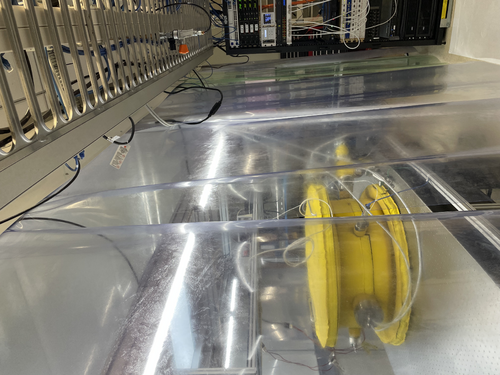
On Friday, we connected the vacuum chamber with the Cymac. |
| Attachment 1: IMG_7916.jpeg
|
|
| Attachment 2: IMG_7915.jpeg
|
|
| Attachment 3: IMG_7917.jpeg
|
|
|
515
|
Tue Feb 18 10:02:16 2025 |
Xuesi Ma | Update | | Group Meeting Slides 2/18/2025 |
https://docs.google.com/presentation/d/1WiV2VqS0BzXNCK6VYYQ-Ty8xlHnzXatQaFbMf1-0rsY/edit?usp=sharing |
|
525
|
Tue Feb 25 10:02:32 2025 |
Xuesi Ma | Update | | |
1424039912.625576 2025/02/19 22:38:14 UTC Time start
24V 2.8A right after start all 8 elements
1424044804.902443 2025/02/19 23:59:46 UTC Time stop
24V 1.8A right before stop all 8 elements
0.1A right before start and right after stop
note: turned on briefly to check current right before stop
2/20 RGA Scan
spikes??
1424129207.857777 2025/02/20 23:26:29 UTC Time start
24V 2.9A right after start all 8 elements
1424140789.856096 2025/02/21 02:39:31 UTC Time stop
24V 1.7A right before stop all 8 elements
0.1A right before start and right after stop
2025/02/21 02:43:19 UTC
Main chamber pressure: 1.54e-8
RGA chamber pressure:5.06e-9
spikes are due to loose connection between connectors.
1424210410.173863 2025/02/21 21:59:52 UTC Time start
24V 2.9A right after start all 8 elements
1424218357.96404 2025/02/22 00:12:19 UTC Time stop
24V 1.7A right before stop all 8 elements
each elements: 0.3A (0.2A increment)(all)
0.1A right before start and right before stop
2/24 RGA Scan
1424467918.129082 2025/02/24 21:31:40 UTC Time start
12V 2A right after start all 8 elements
1424478936.635821 2025/02/25 00:35:18 UTC Time stop
12V 1.6A right before stop all 8 elements
each elements: 0.4A (0.2A increment)(all)
0.2A right before start
rise time: A(1-exp(-t/tau))+B
fall time: Aexp(-t/tau) +B |
| Attachment 1: resistance_vs_time_all_channels_all_time.pdf
|

|
| Attachment 2: temperature_vs_time_all_channels_all_time.pdf
|

|
| Attachment 3: resistance_vs_time_rise_time.pdf
|

|
| Attachment 4: resistance_vs_time_fall_time.pdf
|

|
|
529
|
Tue Mar 4 03:33:18 2025 |
Xuesi Ma | Update | | Update |
Spikes Appear Again, need to address it systematically.
Power on and off before reaching steady state ✔
At 12V, the rise and fall time of heater elements are different from 24V.
Initial guess is due to temperature in the chamber. However, it does not seem to be the case, 24V with 30c have the same hall time as 24V at lower temperature.
Attached are some graphs for rise and fall time
After a weekend of powering on, the main chamber pressure stabilized in the UHV region.
Temperature in the chamber seems also not to change. |
| Attachment 1: resistance_vs_time_all_channels_all_time.pdf
|

|
| Attachment 2: resistance_vs_time_rise_time.pdf
|

|
| Attachment 3: resistance_vs_time_fall_time.pdf
|

|
| Attachment 4: resistance_vs_time_rise_time_12V.pdf
|

|
| Attachment 5: resistance_vs_time_fall_time_12V.pdf
|

|
| Attachment 6: resistance_vs_time_fall_time_24V_30c.pdf
|

|
|
539
|
Tue Mar 11 10:43:57 2025 |
Xuesi Ma | Update | | |
Continue investigation in the spikes
Pulsed ADC with a function generator and find no spikes. Rules out ADC for causing the spikes
Loopback test that bypasses the FROSTI Chassis shows spikes (spikes happened on all channels at the same time)
Next step is to bypass the AI Chassis to find the source of the spikes |
| Attachment 1: 20250310_171936.jpg
|
|
|
544
|
Mon Mar 31 15:41:56 2025 |
Xuesi Ma | Update | | |
The result from AI Chassis bypass test showed that the AI Chassis may be the problem. There are no spikes from DAC's direct output.
All chassis except timing chassis are turned off. Power supplies for 24V, 18V, and -18V are turned off
The AI chassis has been taken out of the rack for further inspection
Refer to:
https://dcc.ligo.org/LIGO-E2300117
https://dcc.ligo.org/cgi-bin/private/DocDB/ShowDocument?.submit=Identifier&docid=D2300124&version= |
|
545
|
Tue Apr 1 11:47:08 2025 |
Liu | Update | | |
|
| Attachment 1: Thermal_state_decoder_update.pdf
|

|
|
547
|
Mon Apr 7 13:28:49 2025 |
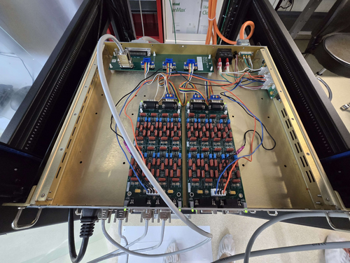
Xuesi Ma | Update | | |
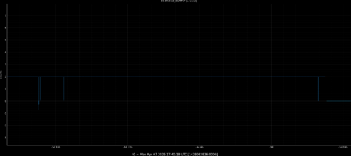
Test 1: Adapter Board Connected to Filter Board
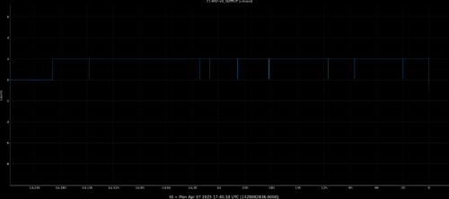
- Setup: AI Chassis is powered on. Signal is measured directly from the adapter board. All other ports on the adapter board are connected to the filter board.
- Observation: Two distinct spikes observed at the beginning of the measurement.
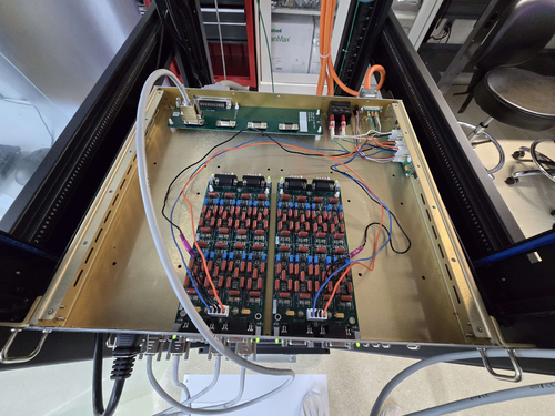
Test 2: Adapter Board Disconnected from Filter Board
- Setup: AI Chassis remains powered on. Signal is again measured directly from the adapter board. This time, the remaining ports on the adapter board are not connected to the filter board.
- Observation: Multiple spikes observed, distributed evenly across the entire measurement.
Test 3: Isolation Test with Spare Adapter Board (ongoing)
- Setup: Suspecting the original adapter board may be faulty, a spare adapter board is used for comparison. Signal is measured directly from this spare board.
-
Update, 04/08/25, Tue 17:30
Took the old adapter board out of the AI chassis and and used it to connect DAC to AA chassis. If no spikes are seen, it means that the glitches are not originating from this board.
Also checked al the previous spikes using the raw data (65536 Hz sample rate). The duration of the glitches are ~1 second, despite the previous guess that they are happening in the Milli-second scale.
|
| Attachment 1: 20250403_151946.jpg
|
|
| Attachment 2: ELOG_Spike_adapter_filter_on.png
|
|
| Attachment 3: 20250404_143624.jpg
|
|
| Attachment 4: ELOG_Spike_adapter_isolate.png
|
|
| Attachment 5: 20250407_105846.jpg
|
|
|
553
|
Tue Apr 15 11:13:43 2025 |
Xuesi Ma | Update | | |
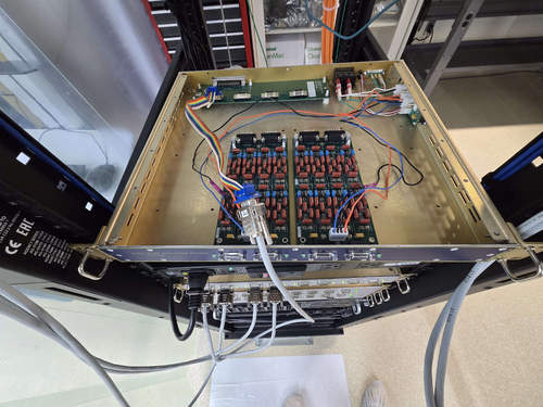
Test 4: AI Chassis ground isolation
- Setup: AI Chassis isolated from the ground with readout directly connected to adapter board
- Observation: No spike observed.
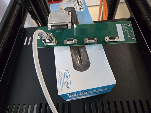
Test 5: Ribbon cable check
- Setup: AI Chassis remains isolated from the ground. The signal is measured after the ribbon cable. (Attachment 3)
- Observation: No spike observed.
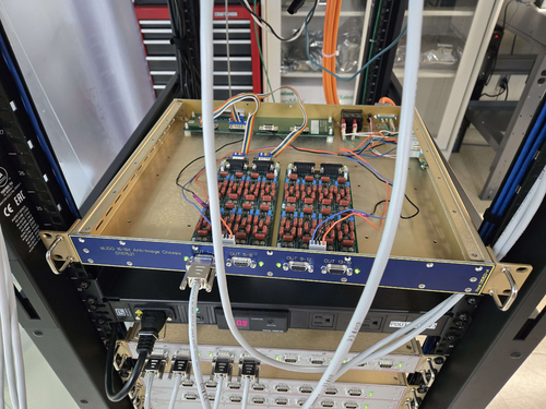
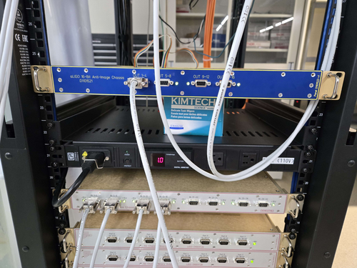
Test 6: Single ground connection check
- Setup: AI chassis powered on but remains isolated from the frame. The signal is measured from the output of the AI Chassis. (Attachment 1 ,2)
-
- Observation: No spike observed.
|
| Attachment 1: 20250414_120428.jpg
|
|
| Attachment 2: 20250414_120423.jpg
|
|
| Attachment 3: 20250411_163105.jpg
|
|
|
559
|
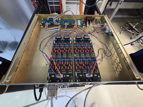
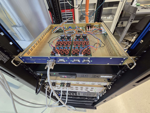
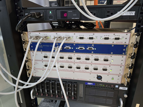
Tue Apr 22 12:08:46 2025 |
Xuesi Ma | Update | | |
Test 7: Reconnect ribbon cables
- Setup: Reconnect all the ribbon cables, and turned on the AI Chassis while isolated rack
- Observation: No spike observed.
Test 8: Reconnect to rack
- Setup: Reconnect the AI Chassis to the rack.
- Observation: No spike observed.
Test 9: Restore to original position.
- Setup: CLose up the AI Chassis, and put it back to its original location.
-
- Observation: No spike observed.
|
| Attachment 1: 20250415_161755.jpg
|
|
| Attachment 2: 20250416_174640.jpg
|
|
| Attachment 3: 20250422_105614.jpg
|
|
|
572
|
Tue May 6 13:19:31 2025 |
Xuesi Ma | Update | | |
|
| Attachment 1: resistance_vs_time_RV_rise_time_24.pdf
|

|
| Attachment 2: resistance_vs_time_all_channels_all_time_RV.pdf
|

|
|
576
|
Tue May 13 12:35:01 2025 |
Xuesi Ma | Update | | |
|
| Attachment 1: resistance_vs_voltage_all.pdf
|

|
| Attachment 2: resistance_vs_voltage_overlay.pdf
|

|
| Attachment 3: resistance_vs_time_all_channels_all_time_RV.pdf
|

|
|
579
|
Mon May 19 10:59:14 2025 |
Xuesi Ma | Infrastructure | | |
Status Update
Previous Status:
All Sorensen power supplies were turned off. The Cymac system was down (all chassis were offline).
If you need more information or assistance in turning them back on, please contact Xuesi Ma.
Update: The systems are now back online.
Note: The Sorensen power supplies’ voltage can now be controlled via channel VEXC8 of the DAC.
If scripting is required, the ezca Python package is highly recommended for interfacing and control.
|
|
583
|
Tue May 27 12:52:22 2025 |
Xuesi Ma | Update | | |
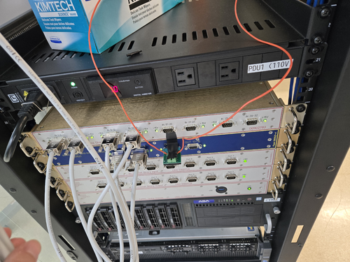
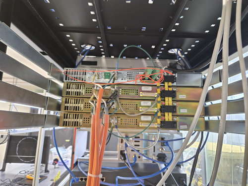
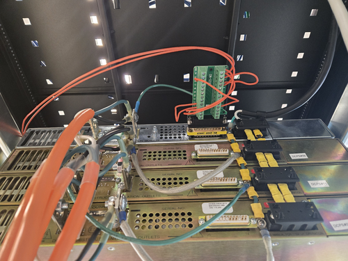
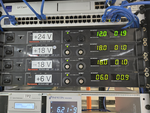
Using the configuration in section 2.11.1 in the Sorensen installation and operation manual (attached below), I'm able to remote control the Sorensen power supply.
I use DAC VEXC8 as the external voltage source and a breakout board to match the configuration of connector J3.
I have recorded 7 cycles (attached below), and am now working on analyzing the data. |
| Attachment 1: operating-manual-Sorensen-DCS-programmable-switching-dc-power-supplies-1kw-dcs-e.pdf
|

|
| Attachment 2: 20250515_171905.jpg
|
|
| Attachment 3: 20250515_164637.jpg
|
|
| Attachment 4: 20250515_164634.jpg
|
|
| Attachment 5: 20250515_164842.jpg
|
|
| Attachment 6: resistance_vs_time_all_channels_all_time_RV_ladder.pdf
|

|
|
586
|
Tue Jun 3 11:54:06 2025 |
Cece Ochoa | Update | | CE Cavity Design Update |
| Update on the design for the CE Cavity Mirrors |
| Attachment 1: CE_Arm_Cavity_.pdf
|

|
|
588
|
Tue Jun 3 13:08:47 2025 |
Xuesi Ma | Update | | |
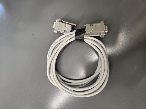
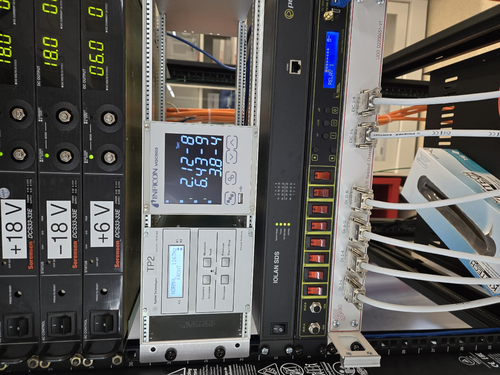
We currently have the parts for a DB9 connector but need parts for a DB25 connector, where did we get the parts for the DB9 connector? We may be able to use the same company for the DB25 connector.
Also need a cable for the connectors. Find a DB9 to DB9 cable in 1129, not sure if I can disassemble it and use just the cable.
The pressure in the vacuum chamber rises to 2.12e-8 torr, which needs baking. |
| Attachment 1: 934.jpg
|
|
| Attachment 2: 933.jpg
|
|
|
589
|
Tue Jun 3 13:16:53 2025 |
Xuesi Ma | Infrastructure | | |
|
Date and Time: Around 3:50 PM on June 2, 2025
Location and Temperature:
- Back of the room 1119, around the working station: 86 °F
- Front of the room 1119, around the doorway: 84.1 °F
- Back of the room 1129, around the working station: 78.6 °F
- Front of the room 1129, around the doorway: 78.3 °F
- In the hallway in front of room 1119: 75.2 °F
|