| ID |
Date |
Author |
Type |
Category |
Subject |
|
726
|
Thu Jul 2 13:27:48 2026 |
Joshua Marmor | Update | General | HBT SURF Update #1 |
| Update on the progress for the HBT measurement. |
| Attachment 1: group-meeting-july-2.pdf
|

|
|
727
|
Thu Jul 2 14:46:19 2026 |
Xuesi | Update | | FROSTI Reflector Design |
Update on the FROSTI reflector design
slides |
|
728
|
Mon Jul 6 18:25:26 2026 |
shane | Update | Inventory | Cleaning/PPE inventory |
|
The cleaning supply/PPE inventory has now been fully updated and the spreadsheet can be viewed here. Any future additions to the lab inventory and new supplies should be added by filling out this form, which will auto-add to the spreadsheet to keep things neat.
|
|
730
|
Thu Jul 9 12:13:02 2026 |
Abhiram Sharma | Update | Interferometer Simulations | |
| Update on MCMC SURF project |
| Attachment 1: Week_2_-_Group_Meeting_Update_Abhi.pdf
|

|
|
731
|
Thu Jul 9 12:27:20 2026 |
Joshua Marmor | Update | General | Week 2 HBT Surf Project |
| Slides for group meeting, updates on HBT measurement |
| Attachment 1: group-meeting-july-9.pdf
|

|
|
733
|
Thu Jul 9 13:35:08 2026 |
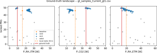
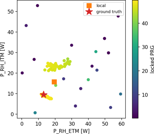
Mary | Update | Interferometer Simulations | |
|
| Attachment 1: gt_Current_gt1_landscape.png
|
|
| Attachment 2: gt_Current_gt1_2d.png
|
|
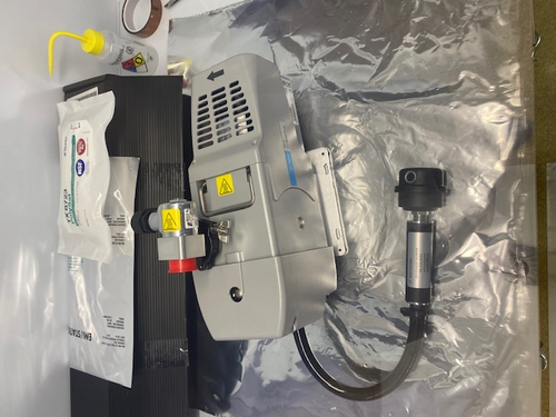
|
736
|
Thu Jul 16 10:29:19 2026 |
Joshua | Update | General | HBT SURF Update #3 |
[Joshua, Mary, Ma, Abhi]
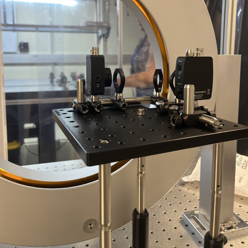
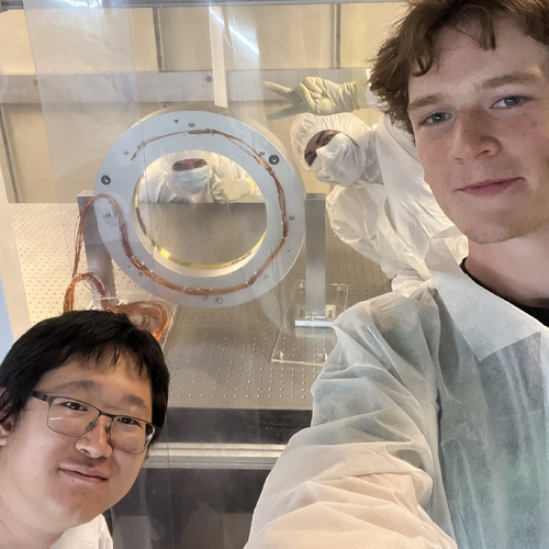
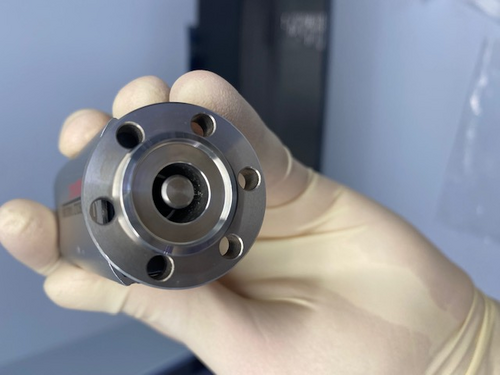
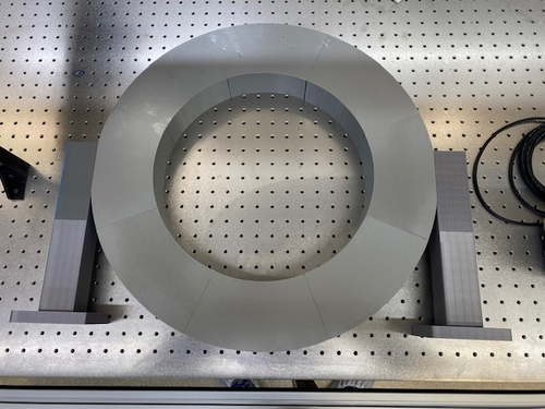
On Wednesday (7/15), the particle count measurement was sufficient, so the FROSTI was transferred into the cleanroom. We unmounted it from the plastic base, and secured it to the optical table. We also transferred the neccessary parts for the HBT setup and began assembly. The breadboard was built first (except for the lenses/beamsplitter) and mounted the the optical posts which will hold it. We placed the beamsplitter as close as possible to FROSTI without touching, and secured the feet.
It is ready for the lenses/beamsplitter to be cleaned and placed in their mounts. Then we will align the setup for maximum power on the transmissive arm.
|
| Attachment 1: IMG_8060.jpg
|
|
| Attachment 2: IMG_8057.jpg
|
|
|
737
|
Thu Jul 16 10:52:02 2026 |
Joshua | Update | General | HBT SURF Update #3 - group meeting slides |
|
| Attachment 1: group-meeting-july-16.pdf
|

|
|
738
|
Thu Jul 16 13:14:26 2026 |
Cynthia | Update | Interferometer Simulations | LIGO pre-figuring team meeting summary |
| Pre-figuring meeting 7/14:
- the non-uniformity brought by annealing for ETM14 and 11 seems to be higher than expected, this meeting focused on discussing about annealing data for ETM014 and 11 : https://dcc-lho.ligo.org/LIGO-T2600213
-we will receive more data for these, since there are some residual power left in the data/plots shown in the meeting because of the reference sphere, and the exact reference sphere radius is unclear
- reviewed the uniformity plot for HR ETM with TiGe coating again: https://dcc-lho.ligo.org/LIGO-T2600277
- not a lot of updates for ring heater: 40W delivered. Currently lock with 1.5W per segment on ETMy at LHO
- slides for HOM study for 250mW biased profile:
https://docs.google.com/presentation/d/1BWh_skxkCXBu_e_QkXkUs9CdvFIryu7H_jfpCgOenNg/edit?usp=sharing
https://docs.google.com/presentation/d/174XVLLpNpNgnL0uV-dSp6MO5pmZ9Yvnouf8V0LA2zE8/edit?usp=sharing
However, we did not focus on any surface profile related topics in the meeting so it was not presented |
|
739
|
Tue Jul 21 15:47:55 2026 |
Joshua | Update | General | HBT SURF Update #4 - Alignment & First Measurement |
|
HBT Alignment & First Measurement
HBT setup was aligned for maximum power on the transmissive arm, then the beamsplitter was tilted to equalize the power in each arm. Then, we set the board at
Total power: 0.156 V
Power on each photodetector: 0.078 V
We left the FROSTI on and will collect data overnight. If we need more power, we can cut the breadboard notch further.
[Joshua, Mary]
|
|
740
|
Tue Jul 21 17:58:36 2026 |
Pooyan | Update | CDS | Cymac DAQ channel add for long-term recording |
Changed the sample rate of Cymac ADC channels V3 and VREF6 to 65 kHz for long-time recording. (65536 to be exact)
Here is a how-to for future reference:
- On Cymac, open Matlab and go to the medm model at '/opt/rtcds/usercode/models/c1msc.mdl'
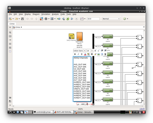
- On the left hand side, there is a DAQ Channel block with text. Any Channel on this list will be recorded to the .gwf frame files as raw data. See alog 592 , and the attached picture.
- I have added all of our current channels to this list, with full sample rate to be recorded, but have commented out the ones that are not in use currently. For future, one can just uncomment the ones that they need to add.
- Make sure that you save the model (by ctrl+S) after making changes
- Complile and install the model following this page.
- Restart the rts services. It's easiest to just restart all via: `sudo systemctl restart rts*`
I have resurrected the automatic backup script for the Cymac files as well. Will start running it in a few days. |
| Attachment 1: Screenshot_20260721_193849.png
|
|
|
741
|
Sun Jul 26 13:07:04 2026 |
Cece | Update | Inventory | Vacuum Part Inventory |
Took a more comprehensive inventory of the vacuum chamber parts on the optical table in 1129. Made note of scratches, chips, stains on each part.
Next steps: update inventory spreadsheet with the annotated photo, check hoses, o-rings, and KF clamps in 1125. |
| Attachment 1: Issues_with_parts.pdf
|

|
|
742
|
Wed Jul 29 23:56:29 2026 |
Cynthia | Update | Interferometer Simulations | Pre-figuring meeting 7/28 summery |
| Pre-figuring meeting 7/14:
- using the change in surface from annealing, Hiro did some study on HOM scattering/losses from just this surface (shown in the email attachmnent O5testmass.pdf. We together went over these results again.
    - ETM11 annealing data to be used: https://dcc.ligo.org/T2600214
- more annealing data: https://docs.google.com/spreadsheets/d/1E138nNZk5b1yPm0g5jmwv_Z9FD9ArQtnlAk1d_1Ce1U/edit?usp=sharing
- Mostly discussed what to do about this annealing surface change when we are polishing the mirror: The idea now is to polish around it (the polish will include the negative of those surface deformation), but it's better to express it in an analytical form to the manufactuer. We try to explore if it is feasible to represent this surface introduced by annealing as Zernike coefficients
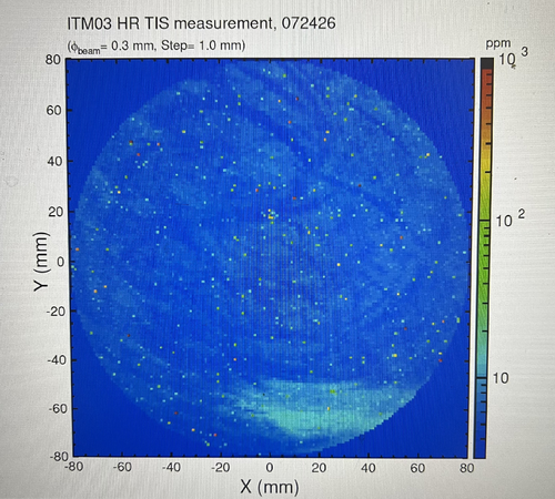
- New ITM meausrement shown as attachment below
- Kevin and Evan will take this surface after annealing as part of their error analysis for their 250mW biased surface profile in the furture, meanwhile I tried to see how will the HOM and PRG conditions change if we don't do anything about this surface, using same analysis we did before:
-
https://docs.google.com/presentation/d/1nkyOmivyaPKkvbgf3TPBjgV2YcgRum7N1EvapgcIMaA/edit?slide=id.p#slide=id.p
|
| Attachment 1: IMG_6504.jpg
|
|
|
743
|
Thu Jul 30 14:15:52 2026 |
Joshua | Update | General | HBT SURF Update #5 - Group Meeting Slides |
| Attached are my group meeting slides and some calculations from Mary which predict the photon bunching cross correlation signal. |
| Attachment 1: group-meeting-slides-july-30.pdf
|

|
| Attachment 2: HBT_V2.pdf
|

|
|
745
|
Thu Aug 6 10:46:49 2026 |
Abhiram Sharma | Update | Interferometer Simulations | MCMC Test with Synthetic Data |
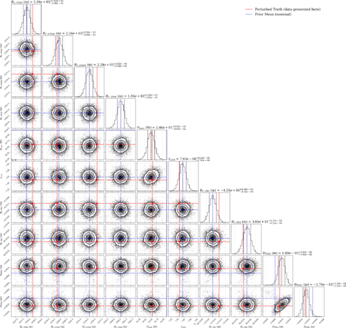
| This corner plot was generated using the base finesse-ligo LLO model for the MCMC forward model. The prior distributions were centered around the base model's parameter values. Then each parameter was slightly perturbed according to their prior width and this perturbed instance of the model was used to generate a list of detector values. Each detector reading was then perturbed with 1% fractional error to simulate detector/calibration uncertainties.
From the plot, the sampler has a hard time recovering the test mass RoC's however it can recover the PRC mirror positions well. |
| Attachment 1: CornerPlot_baseLLO_10Params.svg
|
|
|
746
|
Thu Aug 6 14:39:47 2026 |
Joshua | Update | General | Heating Element Power Data |
This is a measurement done to determine which heating elements output the most power. FROSTI was supplied 33V, and a photodetector was held to the center of each heating element directly at the aperture.
Element #1 (top), RTD0 - 0.33 V
Element #2 (bottom right), RTD1 - 0.21 V
Element #3 (top left), RTD2 - 0.15 V
Element #4 (bottom), RTD3 - 0.33 V
Element #5 (bottom left), RTD4 - 0.31 V
Element #6 (right), RTD5 - 0.25 V
Element #7 (top right), RTD6 - 0.00 V (shorted)
Element #8 (left), RTD7 - 0.31
|
|
748
|
Tue Sep 1 11:50:44 2026 |
Ruaraidh Dumbreck | Update | TCS | COMSOL modeling for the ring heater |
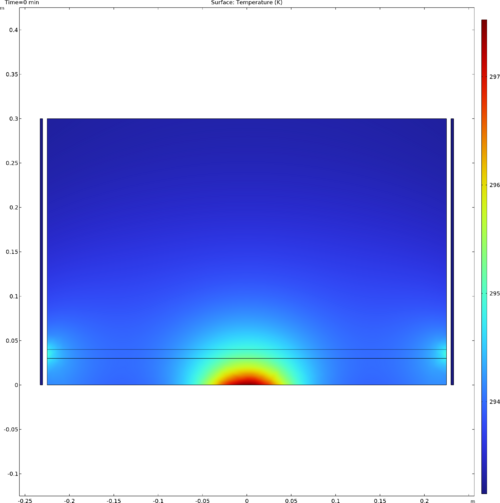
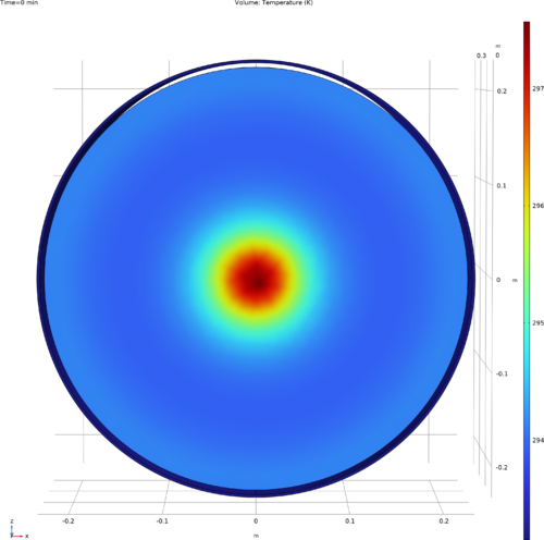
| I’ve set up the base COMSOL model for Cosmic Explorer ITM optics (450 mm diameter × 300 mm thickness). I implemented the absorbed heat power in the Heat Transfer module—using 1 W of self-heating and an exaggerated 150 W ring heater power to make the initial thermal gradients easily visible.
Next, I need to couple the Solid Mechanics physics to compute front-surface thermal expansion, then run a parametric sweep on the ring heater power to find the value that minimizes total thermal distortion." |
| Attachment 1: WithRH2D.png
|
|
| Attachment 2: WithRH3D.png
|
|
|
749
|
Thu Sep 3 10:14:21 2026 |
Ruaraidh Dumbreck | Update | TCS | COMSOL modeling for the ring heater + Shield |
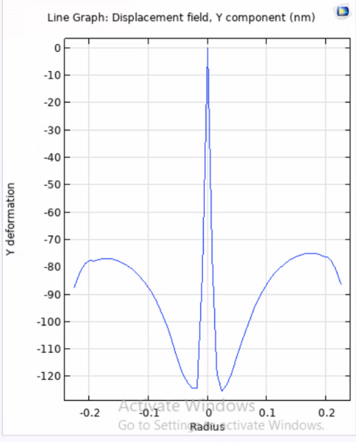
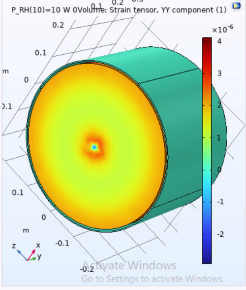
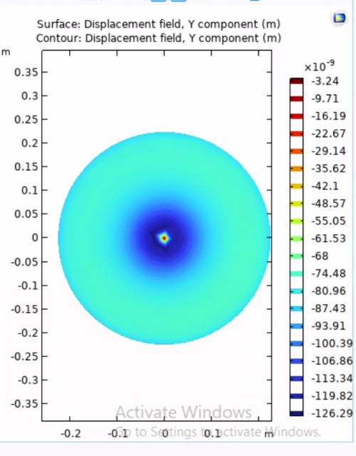
| I had a bit of trouble with the deformation model for the simulation but ive fixed it now, although some of the scales are still in meters. I have seperated the thermal calculation and the thermoelastic deformation into 2 seperate studys. I can parameter sweep the first study but i am currently having issues with the 2nd study that i am trying to troubleshoot.
I have also set im an expression calculator to measure the change in deformation in "v" (the displacement component in the y axis) through the expression "= ABS(vmax)-ABS(vmin)" and im trying to get comsol to return the value of the ring heater power at which this is minimised. Then after this i want to conduct another parameter sweep of ring heater seperation from the barrel and repeat the same previous sweeps so i can try and produce a graph of optimal ring heater power against distance of the shield from the ITM.
im unsure if my method of using the minimum total deformation in v is accurate to finding the ring heater power needed to compensate for the self heating, which is currently set to 1W |
| Attachment 1: 1d.png
|
|
| Attachment 2: 3d.png
|
|
| Attachment 3: 2d.png
|
|
|
750
|
Thu Sep 10 10:45:52 2026 |
Ruaraidh Dumbreck | Update | TCS | COMSOL modeling for the ring heater |
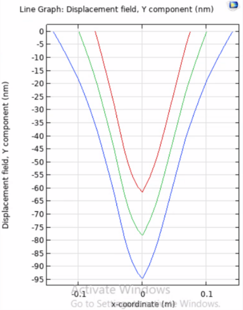
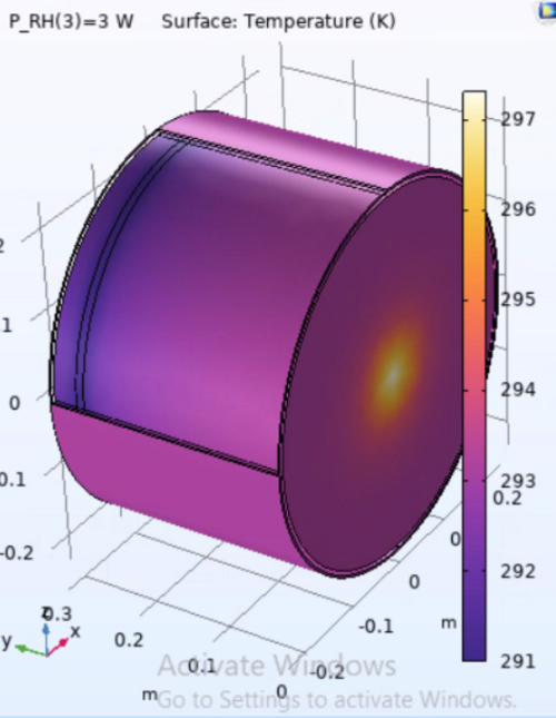
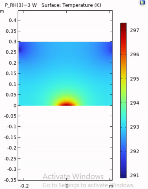
| Since last week, I have put the ring heater on the correct side of the optic and found that the thermal modelling is being limited by the solid mechanics of the optic, particularily the fixed point on the AR face of the optic. I have been looking into different methods of modelling but not found a solution as of yet. The silver lining is that i have managed to tie the displacement to the parameter sweep. i have also started reading and learning Braket notation again ahead of the next step for a true parameter sweep. I will try and see if i can send the file to the COMSOL engineers aswell. I have not yet checked if the displacements are accurate given the powers im simulating, so it is by no means a final result. |
| Attachment 1: plot_3.png
|
|
| Attachment 2: plot_2.png
|
|
| Attachment 3: plot_1.png
|
|
|
751
|
Thu Sep 10 13:05:47 2026 |
Cynthia | Update | Interferometer Simulations | Beam Miscentering PRG Distribution |
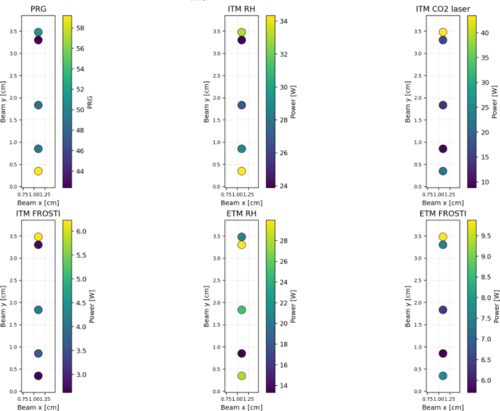
| generated the global optimum PRG, thermal actuator powers for FROSTI Dual for a few points (only 5 y beam position finished running so far but the plot can be generated actively as each new beam position finished running) with the particle swarm code. Only beam is moved around, no point absorbers.
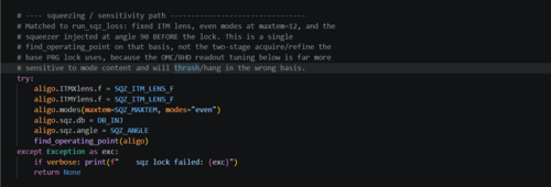
Unsure if the modes can be kept "even" once point absorber and mis-centering is introduced when locking the interferometer in the simulation when simulating quantum noise/squeezing. So The quantum noise distribution is for now still running but running all modes (0-12) |
| Attachment 1: PRG_distribution.png
|
|
| Attachment 2: qn_code.png
|
|
|
752
|
Thu Sep 17 11:52:48 2026 |
Ruaraidh Dumbreck | Update | TCS | COMSOL modeling for the ring heater preliminary run |
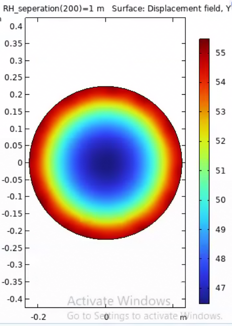
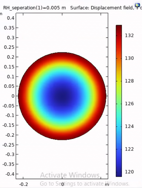
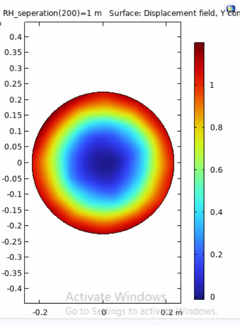
| This week i have fixed the study to model deformation and thermal expansion in 1 study and corrected some errors in the system.
I have seperated the study into 2 simulations. 1 modelling the heat flux of the ring heater, for 1W deposited power, only and another modelling the heat flux of the self induced heating, also 1W deposited power.
since the ring heater heat is deposited closer to the AR face, i made the fixed constraint for this model the middle of the HR face. and since the self heating is primarily operating on the HR face, i made the fixed constraint for this model the middle of the AR face.
I then ran a parameter sweep of the shield seperation from the ITM between 5mm and 1m.
attached are the plots for the HR and AR surface deformation at the 2 extremes for the ring heater heating maps (note, i made an error on the the self heating plots where i didnt move the fixed constraint and only vaired the seperation by 0.1m. I will re run the simulation with these corrections).
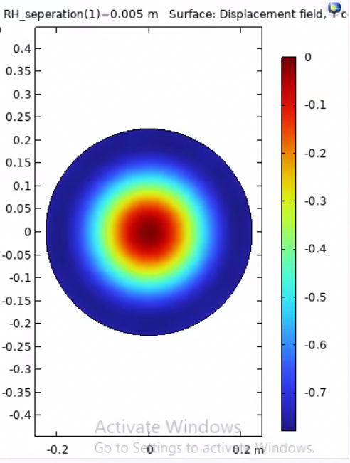
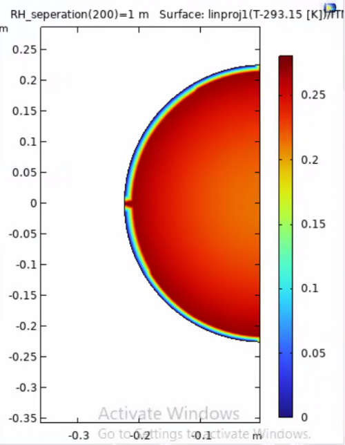
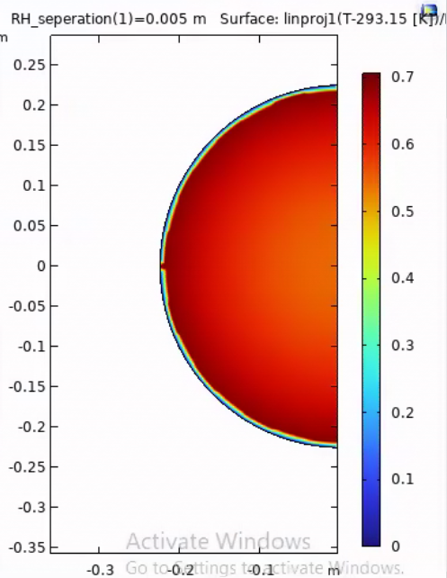
i beleive the models of the displacementr in the y axis look as we would expect, however the 2D heat map may have some mechanical/boundary constraints that need double checked. |
| Attachment 1: AR_surface_deformation_1m.png
|
|
| Attachment 2: AR_surface_deformation_5mm.png
|
|
| Attachment 3: HR_surface_deformation_1m.png
|
|
| Attachment 4: HR_surface_deformation_5mm.png
|
|
| Attachment 5: heat_map_1m.png
|
|
| Attachment 6: heat_map_5mm.png
|
|
|
753
|
Thu Sep 24 14:00:51 2026 |
Ruaraidh Dumbreck | Update | TCS | debugging and troubleshooting |
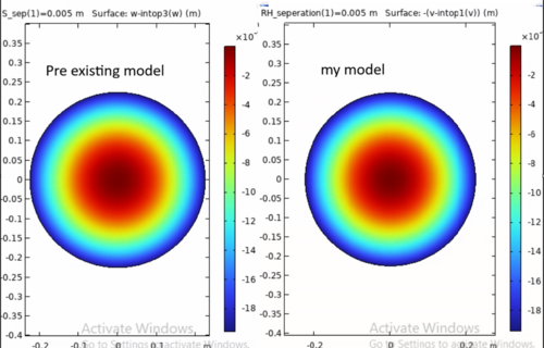
| I am in the process of comparing my model to the pre existing model used for current ligo parameters. the aim is to have 2 studies, 1 where i change the parameters of the existing model to that of A#, remove the CP and add a shield. Another to change my model to the parameter and geometry of the existing ALIGO model (without a CP) and see if our deformation plots produce the same results.
I am having some troubleshooting issues with both models as there appears to be some kind of asymmetric heating happening for the self induced heating. as well as this, i discovered that my model stress doesnt make sense (the optic has more stress the further away the shield is.
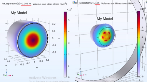
the only positive report i have to show currently is that the AR values for the self induced heating with the shield at its closest point are the same. i will cpntinue to debug these issues. |
| Attachment 1: Screenshot_2026-09-24_134753.png
|
|
| Attachment 2: Screenshot_2026-09-24_135028.png
|

|
| Attachment 3: Screenshot_2026-09-24_135315.png
|
|
|
754
|
Thu Oct 1 13:04:03 2026 |
Ruaraidh Dumbreck | Update | TCS | COMSOL Shield modeling (My model scaled to PRL model parmeters) |
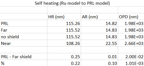
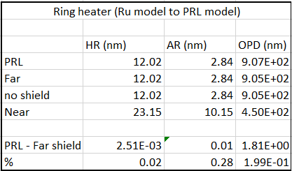
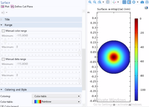
| so i have managed to produce good results for my model. I have managed to produce results that agree withing ~0.2%. The metric im using to compare the 2 models is the results sub plot node->data range. This data range shows the maximum+ minimum values for the data being plotted (example attached). in the case of these graphs one of either the maxima or minima are 0 (depending on orientation of the geometry). I have managed to acheive very close values for HR+AR deformation as well as OPD. These values were calculated using the same method and expression as the PRL model. While im happy i have acheived these results, I am unsure how i have changed the model to acheive this. I updated an older version of the model and this one works very well. so i am currently diagnosing the difference between the working model and the model i was working on for days so identify what happened.
i have not yet managed to confirm the models match when I scale them both up to A+ parameters as of yet, I beleive the reasoning lies in the result of the above diagnosis. |
| Attachment 1: self.png
|
|
| Attachment 2: RH.png
|
|
| Attachment 3: PRL_self_HR.png
|
|
|
10
|
Wed Aug 17 16:04:30 2022 |
Phoebe Zyla | Summary | Lore | Testing the Cartridge Heater and Collecting FLIR Data |
We have tested the heater to find emissivity, mounted the heater system to the optical table, and have taken irradiance maps of the heater projected onto the screen.
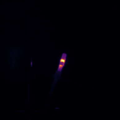
The heater's emissivity was determined by using a thermocouple in conjunction with the FLIR's temperature calibration. To attach the thermocouple to the heater initially, I used Kapton tape and ran both the wires of the heater and the thermocouple through the heater bridge. This allowed for the heater to rest on an optical post and be observed without anyone directly holding it, but there were some measurement issues. The thermocouple had a very wide range of temperatures it was reading, which may have been due to intermittent contact or a short between the two legs of the thermocouple. To solve this and make the temperature measurements more stable, we pried apart the two ends of the thermocouple (to ensure there was no short) and put tape on either side, leaving the end connection bare. This was then taped to the heater, and the thermocouple was much more stable. We also used a K-type thermocouple that has an adhesive tape on it already, which assisted with the intermittent contact as well. With the thermocouple measuring the temperature of the heater, we could point the FLIR directly at the heater and calibrate the emissivity until the FLIR and the thermocouple agreed. Cassidy's emissivity calculator was also used, as I could input a temperature and observe what the emissivity of an area was based on that temperature. We found the emissivity of the heater to be 0.57.
As a note, when observing the heater with the FLIR, it appeared that there was a hot spot in the center, where the Kapton tape sat. Because the Kapton has a different emissivity than the 304 stainless steel of the heater, the FLIR will read it as having a different temperature than it actually does. When using the FLIR in the future, be sure to ascertain whether there is a temperature difference somewhere or if there may be different emissivities.
Additionally, the first heater that I used was taken to a very high temperature and oxidized. The emissivity of this oxidized heater is not known, but could be good information for knowing how oxidation affects these heaters specifically.
To mount the heater system in front of the screen, I used 1/2'' optical posts and the mount I designed using COMSOL's CAD program. The heater was originally 2.5 inches away from the screen, and has since been moved back by an additional two inches so that we could observe the heater side of the screen with the FLIR. We wanted to see what temperature the heater side of the screen was when irradiated by the heater, and how that compared to the camera side of the screen. When the heater ran at 1.12 W of input power, the heater side of the screen had a max temperature of around 29.7 C, and the camera side of the screen read at about 29.5 C. This means that there is very little thermal loss between the two sides of the screen, and any insulation that the screen's adhesive may have is largely negligible. Additionally, the camera was placed at an angle and undetermined distance for these tests, confirming that the temperature measurements compensate well/don’t depend on changes in angle or distance between the camera and the screen. However, there was spots on the back of the screen that the camera was measuring as hot spots where there shouldn’t have been any. I have included an example below. It would be useful to run a test where the camera is directly on the back of the screen without the heater to characterize the screen and see if the hot spots are physically present on the screen or if this is an artifice of the camera because of something like angle of viewing.
Taking irradiance maps of the screen was straightforward. After checking that the emissivity of the screen is 0.99 by viewing it at room temperature, we monitored the max temperature while slowing increasing the wattage the heater was running at. There is not a large change until the heater is at around 95 C, at which point the screen began to rise in temperature from 27 C to 28 C. We took measurements of this while the heater was 2.5 and 4.5 inches away from the screen. The irradiance map has a very symmetrical and circular shape, but does not have the ring pattern that we expected. There may be a few reasons for this: there could be some conduction between the two sides of the screen that is causing the pattern to spread further, the heater setup may not be as ideal as it was modeled to be, or there could be a different, unknown issue.
TO DO:
- It would be useful to run a test of the camera in multiple different positions to ensure our conclusion that the camera’s measurements don’t depend on angle or distance (or that these factors are well accounted for in the current temperature calculations) is correct.
- Measure the back of the screen straight on to identify bright spots and possible reasons as to their appearance.
- Recalibrate camera to ensure it is still correct after testing in multiple positions.
- Take another irradiance map of the screen at a higher input power, as well as moving the heater close/further away to try and replicate the COMSOL irradiance maps. It would be useful to also redo the COMSOL modeling at lower powers and variable distances.
Pictures included of full table setup, the heater mount, the heater with Kapton tape attaching the thermocouple as well as FLIR's measured irradiance map. |
| Attachment 1: Screenshot_(74).png
|
.png.png "Screenshot_(74).png")
|
| Attachment 2: Screenshot_(75).png
|
.png.png "Screenshot_(75).png")
|
| Attachment 3: Screenshot_from_2022-08-15_11-24-40.png
|
|
| Attachment 4: AcquisitionImage(Aug-15-2022_14_16).jpg
|
.jpg.png "AcquisitionImage(Aug-15-2022_14_16).jpg")
|
|
19
|
Fri Feb 3 13:04:04 2023 |
shane | Summary | General | clean room particle counts 1/25/23 |
| Clean room count graphs for each zone (as of January 25, 2023) attached |
| Attachment 1: cleanroomcountsJan25.pdf
|

|
|
29
|
Mon Feb 13 18:57:53 2023 |
Aiden | Summary | General | Clean and Bake batch 2 |
| Cleaned second batch of SS parts with liquinox for 20 min. Then put in oven for 5 steps; 1. Ramp, 100 degC, 15 min 2. Const, 100 degC, 30 min 3. Ramp, 200 degC, 30 min 4. Const, 200 degC, 48 hours 5. Ramp, 25 degC, (off). |
|
31
|
Tue Feb 21 17:51:04 2023 |
Aiden | Summary | General | Clean and Bake batch 4 |
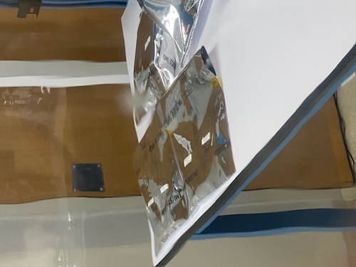
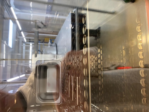
| Bagged and Tagged batch 3 parts by placing no more than two part numbers per bag and taped them with kapton tape and labeled them with their name and part number. Then placed them in the clean room on the work bench.
Cleaned batch 4 parts with liquinox and placed the into the oven for 5 steps;
1. Ramp to 100 degC in 15 minutes.
2. Dwell at 100 degC for 30 minutes.
3. Ramp to 200 degC in 30 minutes.
4. Dwell at 200 degC for 48 hours.
5. Turn off and cool down to room temperature.
To see the specific parts in batch 4 please refer to the Clean and Bake spread sheet on the Richardson lab page: https://docs.google.com/spreadsheets/d/19gnv1q9l64gxnq76KfcXizbqShJfK0ayn2Js1SiAZok/edit#gid=1765414234 |
| Attachment 1: IMG_4148.jpg
|
|
| Attachment 2: IMG_4147.jpg
|
|
|
38
|
Tue Feb 28 19:37:22 2023 |
Aiden | Summary | General | Clean and Bake batch 5 |
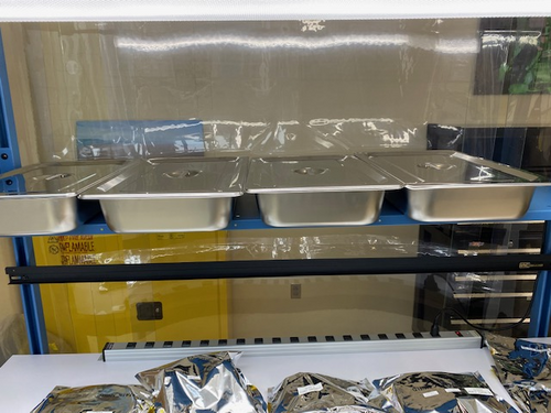
| Bagged and Tagged batch 4 parts by placing no more than two part numbers per bag and taped them with kapton tape and labeled them with their name and part number. Then placed them in the clean room on the work bench. Cleaned batch 5 part (Viton O-Ring) with liquinox and placed the into the oven for 5 steps; 1. Ramp to 100 degC in 15 minutes. 2. Dwell at 100 degC for 30 minutes. 3. Ramp to 180 degC in 30 minutes. 4. Dwell at 180 degC for 48 hours. 5. Turn off and cool down to room temperature. To see the specific parts in batch 5 please refer to the Clean and Bake spread sheet on the Richardson lab page: https://docs.google.com/spreadsheets/d/19gnv1q9l64gxnq76KfcXizbqShJfK0ayn2Js1SiAZok/edit#gid=1765414234
Hand cleaned stainless steel containers and silver coated screws. Designated each container with its contents with the label maker and placed inside the clean room. Should be noted that the fasteners were very clean before the hand cleaning and showed not dirt on the wipes. Added these parts to the clean and bake data base sheet and designated the type of cleaning as "rough cleaning". Gabriella helped with this cleaning and today was her first day in the lab. |
| Attachment 1: IMG_4168.jpg
|
|
| Attachment 2: IMG_4169.jpg
|
|
| Attachment 3: IMG_4170.jpg
|
|
|
42
|
Fri Mar 3 19:13:33 2023 |
Aiden | Summary | General | Clean and Bake Batch 6 |
| Started to clean the dirtiest of the valves. I could not finish but I definitely made good progress on it. The MDC valve is very dirty and there are many places I could not reach with my fingers. I used Acetone and IPA for this first round of cleaning on it.
I also was going to bag the viton O-Ring from the previous Batch, however it seems to have broken during the bake and I am leaving it inside the oven for now. |
| Attachment 1: IMG_4173.jpg
|
|
| Attachment 2: IMG_4174.jpg
|
|
|
47
|
Wed Mar 8 19:29:00 2023 |
Aiden | Summary | General | Clean and Bake batch 7 |
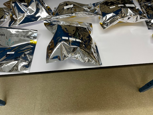
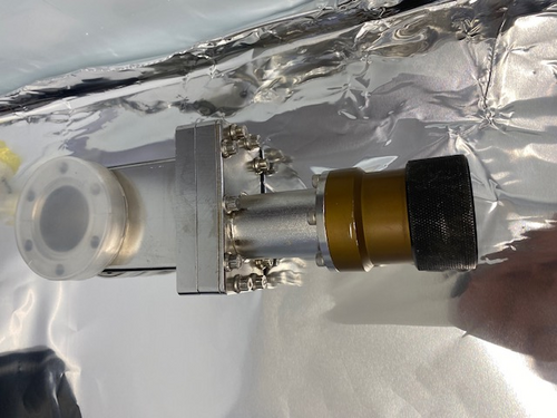
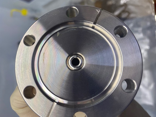
| Today gave another cleaning to the MDC gate valve. It is still very dirty an will need more cleaning. I also cleaned the other 3 valves and the argon leak. These are also in bags inside the clean room. I cleaned them by hand with IPA wipes and had to specifically give the MDC up to air valve a harder clean with acetone as it was not getting clean with the IPA. This valve still has a ring around the face as shown in the first image. Be very cautious when moving the parts in the large ESD bag, it may be heavy and the parts will move inside. |
| Attachment 1: IMG_4180.jpg
|
|
| Attachment 2: IMG_4182.jpg
|
|
|
51
|
Tue Mar 14 18:21:41 2023 |
Aiden | Summary | General | Clean and Bake batch 8 |
| Starting off Peter and I refilled the deionized water barrel.
Then Aiden Cleaned and Bake the FROSTI arms and bases in liquinox for 5 minutes. Then placed them in the oven where they will undergo the following steps;
1. Ramp to 100 degC in 15 min.
2. Dwell at 100 degC for 30 min.
3. Ramp to 120 degC in 30 min.
4. Dwell at 120 degC for 48 hours.
5. OFF
Also cleaned the 2.75 MDC Gate valve for 20 minutes (10 minutes each side) in liquinox. It looks significantly cleaner in areas I could not reach before. However some areas like the flat bottom threaded holes are still very dirty. I also made sure to dry it thoroughly and wrapped it in UHV foil until I further cleaning is decided. |
|
52
|
Fri Mar 17 19:46:39 2023 |
Aiden | Summary | General | Clean and Bake batch 9 |
| Bagged and Tagged the reflector arms and bases and placed them inside the clean room. Total of 2 bags used. Cleaned and Baked parts in batch 9 on the spread sheet and used the following procedure;
1. Ramp to 100 degC in 15 min.
2. Dwell at 100 degC for 30 min.
3. Ramp to 200 degC in 30 min.
4. Dwell at 200 degC for 48 hours.
5. OFF
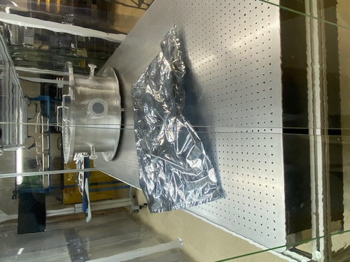
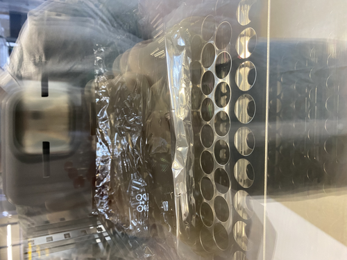
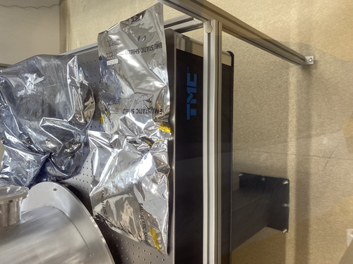
Also soaked the 2.75" CF gate valve in acetone to try and clean the open threads around the part. Then cleaned it in the ultrasonic washer with liquinox for 20 minutes (10 minutes each side). It looks better than it used to but the threads still seem to be the problem and will probably need even further cleaning. |
| Attachment 1: IMG-4208.jpg
|
|
| Attachment 2: IMG-4209.jpg
|
|
|
60
|
Mon Apr 3 17:04:05 2023 |
Aiden | Summary | General | IDP Scroll Pump Assembly |
| Aiden installed the isolation valve and the exhaust silencer kits on the IDP-3 Scroll pump. The entire assembly still needs to be wiped down but overall no residue came off when putting on the kits. |
| Attachment 1: IMG_4244.jpg
|
|
|
69
|
Wed Apr 12 10:53:02 2023 |
Aiden | Summary | General | Valve Cleaning |
| Bagged and Tagged the parts from batch 10 and placed them inside the clean room.
Then cleaned the last gate valve in liquinox for 20 minutes (10 minutes each side). Then dried the valve, bagged, tagged, and placed it inside the clean room. |
|
72
|
Mon Apr 17 17:06:49 2023 |
Aiden | Summary | General | Clean and Bake batch 11 |
| Cleaned the Viton O-Ring for the main chamber in Liquinox for 10 minutes. Then put it in the oven to back for;
1. Ramp to 100 degC in 15 min.
2. Dwell at 100 degC for 30 min.
3. Ramp to 180 degC in 30 min.
4. Dwell at 180 degC for 24 hours.
5. Off
Note: There were three viton -rings in the bag sent to us. I cleaned and baked 2 of them and left the third in the bag. |
| Attachment 1: IMG_4262.jpg
|
|
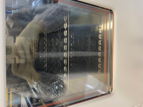
|
77
|
Mon Apr 24 17:38:45 2023 |
Aiden | Summary | General | Clean and Bake Batch 12 |
| Today I Bagged and tagged the o-rings from batch 11 and placed them inside the clean room. I also cleaned batch 12 parts in liquinox for 10 minutes and them placed them into the oven where they will undergo the following steps;
1. Ramp to 100 degC in 15 min.
2. Dwell at 100 degC for 30 min.
3. Ramp to 200 deg C in 30 min.
4. Dwell at 200 deg C for 48 hours.
5. Off |
| Attachment 1: IMG_4269.jpg
|
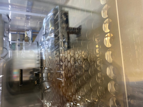
|
| Attachment 2: IMG_4268.jpg
|
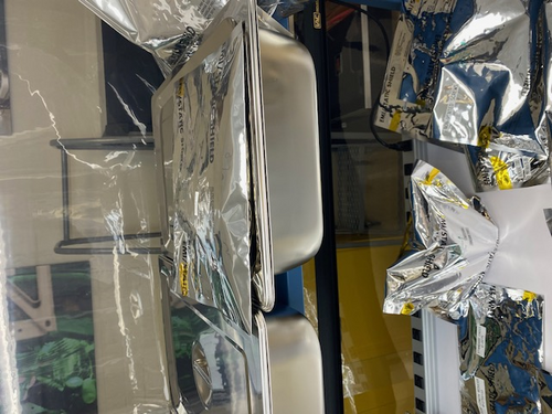
|
|
80
|
Thu Apr 27 09:48:34 2023 |
Aiden | Summary | General | Batch 12 Bagging |
| I took batch 12 out of the oven and put them in a bag and placed the bag inside the clean room in the first large stainless steel container.
I also looked at the small gauge that we felt like needed to be baked and I can confirm that without further cleaning around the inside of the gauge it should not be connected to the main vacuum. I have attached a photo of the inside of the gauge. |
| Attachment 1: IMG_4279.jpg
|
|
| Attachment 2: IMG_4278.jpg
|
|
|
86
|
Fri Apr 28 19:39:19 2023 |
Cao | Summary | General | Clean and Bake Leybold TTR 91 Pirani Gauge |
| Quote: |
| I took batch 12 out of the oven and put them in a bag and placed the bag inside the clean room in the first large stainless steel container.
I also looked at the small gauge that we felt like needed to be baked and I can confirm that without further cleaning around the inside of the gauge it should not be connected to the main vacuum. I have attached a photo of the inside of the gauge. |
Following the problem with contamination particles observed in the the Leybold thermovac TTR 91, we have taken the following step to clean the gauge:
- Wipe with IPA-wetted Vectra Alpha: Cover the tip of a ziptide with Vectra Alpha wipe corner that has been wetted with IPA, push the wipe around and remove visible particulates
- Fill the gauge flange with IPA: (following Jon's recommendation to use Lesker's procedure for cleaning their Pirani gauge), flip the gauge up such that the CF flange points upward, fill the flange with IPA all the way up. Use the tip of a SSTL tweezer to agitate the IPA. Let it sits for 20 minutes, agitate every 5 minutes. After 20 minutes, pour the IPA out then spray with dry pure nitrogen
- Passive drying : Let the gauge sit inside the flowbench for 3 hours (3:30 pm to 6:30 pm)to ensure all IPA has evaporated
- Baking : Leave the gauge in oven at 50 degree C for 48 hours (maximum allowed temperature is 65 deg C, we use 50 deg C to ensure we are well below this limit). Baking started at 7pm, should finish on Sunday 7pm and ready for assembling to vacuum chamber on Monday morning
|
|
111
|
Wed May 31 16:18:41 2023 |
Aiden | Summary | General | Mock FROSTI |
| Finished assembly on the Mock FROSTI so it is ready for the fit test at LIGO lab. |
| Attachment 1: IMG_4394.jpg
|
|
|
121
|
Tue Jun 13 13:25:05 2023 |
Aiden | Summary | Clean & Bake | Clean and Bake Batch 13 |
| Cleaned and Baked the new 1.33" and 2.75" blanks for the vacuum system. Cleaned them with liquinox in the ultra sonic washer for 10 minutes. Then dried them with nitrogen. Then put the two stainless steel parts into the oven for the following steps;
1. Ramp to 100 degC in 15 minutes
2. Dwell at 100 degC for 30 minutes
3. Ramp to 200 degC in 30 minutes
4. Dwell at 200 degC for 48 hours
5. Turn off |
|
148
|
Thu Jul 6 16:16:03 2023 |
Aiden | Summary | VAC | Vacuum Chamber Baking Update |
Pressure Measured Before Removing Gauge 2.31 E-7 Torr.
Went in and turned on the heating tape in increments of 30 degC until 120 degC was reached. I will let it equilibrate over night and then asses whether or not the chamber can be raised to 150 degC without having the flange to the turbo pump reach over 120 degC as it is not recommended for that flange to be any hotter.
If it can safely be raised to 150 degC, then only 2 days of baking is necessary. If 120 degC is the bake temperature, a week will be needed.
|
|
291
|
Mon Dec 11 16:20:17 2023 |
Jon | Summary | TCS | FROSTI Assembly Procedure |
Below is the procedure we will follow to assemble the FROSTI prototype.
- Install SS guide rods and bottom Macor spacers in bottom reflector
- Install AlN elements on top of bottom Macor spacers
- Install upper Macor spacers on top of AlN elements
- Feed unterminated power and RTD leads through slots in upper reflector
- Install upper reflector, using guide rods to slowly lower into position
- Install vented SS bolts for reflectors; Macor bolts for heater elements
- Remove SS guide rods
- Bundle power and sensing cable with PEEK cable ties and SS cable mounts
- Terminate power and sensing cable bundles with PEEK DB25M connectors
|
|
312
|
Wed Jan 31 14:37:26 2024 |
Shane | Summary | CDS | path directions for CyMAC model and parts library |
| Path to cds parts library in Matlab simulink: /usr/share/advligorts/src/src/epics/simLink. File name CDS_PARTS.mdl
Path to user models: /opt/rtcds/usercode/models, using file name c1msc.mdl |
|
472
|
Thu Nov 14 10:46:20 2024 |
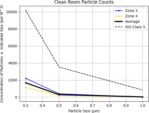
Luke | Summary | Cleanroom | Cleanroom cleaning |
[Luke, Luis, Michael]
cleaning cleanroom and particle count
- 8:30 am: started particle count
- zone 3:
- 0.3 u: 1195
- 0.5 u: 177
- 1.0 u: 132
- zone 4:
- 0.3 u: 619
- 0.5 u: 0
- 1.0 u: 0
- 9:00 am: began surface check and wipedown, including softwalls
- 9:35 am: started vacuuming the floor
- 9:43 am: finished vacuuming the floor
- 9:45 am: started mopping the floor
- 9:55 am: finished mopping the floor
- 9:56 am: started cleaning the buckets
- 10:00 am: started mopping with IPA wipes
- 10:05 am: finished mopping with IPA wipes
- 10:20m: started particle count
- zone 3:
- 0.3 u: 2213
- 0.5 u: 398
- 1.0 u: 0
- zone 4:
- 0.3 u: 1150
- 0.5 u: 177
- 1.0 u: 44
|
| Attachment 1: partical_count_final.png
|
|
|
478
|
Wed Nov 27 12:27:45 2024 |
Luke | Summary | VAC | Summary of vacuum work |
[Luke, Luis]
Update of current state of vacuum chamber
Current temp: 24°C
Current pressure: Main 1.77e-8, RGA 5.3e-9 [torr] (Gate valve open)
Summary of recent work-->
To try and reduce the leak in the turbo pump by reducing cross-connection, we replaced the copper gasket. This made no improvement to the leaks.
Initially: 1.9e-9 --->
Left side: 1.33e-9, Right side: 3.37e-9 (Gate valve open)
This is still a significant leak. We have tried to tighten the bolts further, but they are as tight as reasonably possible.
Things of note: While examining the knife edges, we found some very slight imperfections on the reducing cross's flange as seen in 474. This could be the source of our leak. We have replaced this gasket 1-2 times already and consistently have a slight leak. This imperfection is on the right side of the flange, which would be consistent with the measurements above.
Unless we want to use the liquid sealant or replace the gasket with an annealed gasket, we could try baking the system again, as this allowed us to reach UHV in the main volume before. It also allowed us to pass the RGA scan, which we are currently failing. (see attached) |
| Attachment 1: 2024-11-27_PostBake1_ArO.png
|

|
|
497
|
Wed Jan 8 17:35:57 2025 |
Luke | Summary | Cleanroom | Cleanroom cleaning |
[Luke, Tyler, Cynthia, Shane, Michael]
Summary of Cleaning Activities:
We began cleaning Room 1119 at 2:00 PM.
At 2:30 PM, we moved to Room 1129 and continued cleaning.
Cleaning tasks included wiping down dust-collecting surfaces and vacuuming the floors.
Once the labs were clean, we proceeded to the cleanroom.
- Wiping down surfaces and soft walls
- Vacuuming, mopping the floor, and finishing with IPA wipes
Particle Count Measurements:
- Pre-cleaning (2:30 PM):
- Zone 3:
- 0.3 µm: 973
- 0.5 µm: 354
- 1.0 µm: 132
- Zone 4:
- 0.3 µm: 486
- 0.5 µm: 177
- 1.0 µm: 0
- Post-cleaning (4:10 PM):
- Zone 3:
- 0.3 µm: 619
- 0.5 µm: 132
- 1.0 µm: 0
- Zone 4:
- 0.3 µm: 397
- 0.5 µm: 0
- 1.0 µm: 0
|
| Attachment 1: partical_count_250108.png
|

|
|
500
|
Tue Jan 21 10:12:02 2025 |
Luke | Summary | General | Frosti toy model |
[Luke, Liu]
Over the winter break I have been working on this desmos toy model of the Frosti. There are still a few rough spots but I belive that it is a good visual representation of a 2D slice of the frosti. |
|
507
|
Sat Feb 1 17:25:52 2025 |
Luke | Summary | General | Cleanroom cleaning |
[Luke, Cece, Luis]
Particle Count Measurements:
- Pre-cleaning (12:15 PM):
- Zone 3:
- 0.3 µm: 1325
- 0.5 µm: 265
- 1.0 µm: 0
- Zone 4:
- 0.3 µm: 618
- 0.5 µm: 132
- 1.0 µm: 44
- Started Cleaning (3:20 pm)
- Finished Cleaning (4:20 pm)
- Post-cleaning (4:35 PM):
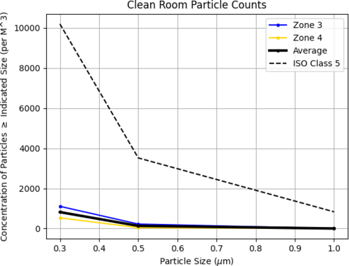
- Zone 3:
- 0.3 µm: 1106
- 0.5 µm: 221
- 1.0 µm: 0
- Zone 4:
- 0.3 µm: 530
- 0.5 µm: 44
- 1.0 µm: 0
|
| Attachment 1: 20250131_particalcount.png
|
|
|
509
|
Fri Feb 7 12:25:56 2025 |
Luke | Summary | VAC | Started bake |
[Luke, Luis]
The vacuum chamber is currently baking.
We stepped up to 120°C by increments of 30°C starting at 60°C. We took about an hour break at 90°C to let the temperatures equilibrate.
Current state as of 12:20:
The gate valve is open, the calibrated Argon leak is open, and the filament of the RGA is on.
The temperatures are as follows:
PID right barrel upper: 113°C, RGA volume: 120°C
PID left barrel lower: 121°C, Lid: 114°C
The lower temperatures should climb as the whole system heats up.
|
|
520
|
Sun Feb 23 12:11:43 2025 |
Luke | Summary | Cleanroom | Cleanroom cleaning |
[Luke, Mary, Luis]
Particle Count Measurements:
- Pre-cleaning (8:40 am):
- Zone 3:
- 0.3 µm: 441
- 0.5 µm: 44
- 1.0 µm: 0
- Zone 4:
- 0.3 µm: 353
- 0.5 µm: 176
- 1.0 µm: 44
- Started Cleaning (3:16 pm)
- Finished Cleaning (4:10 pm)
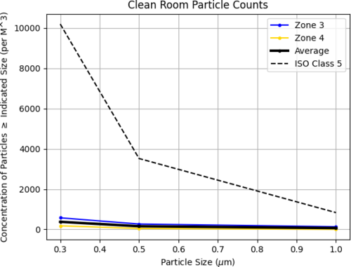
- Post-cleaning (4:15 pm):
- Zone 3:
- 0.3 µm: 574
- 0.5 µm: 265
- 1.0 µm: 132
- Zone 4:
- 0.3 µm: 177
- 0.5 µm: 44
- 1.0 µm: 0
|
| Attachment 1: partical_count_2-21-25.png
|
|