| ID |
Date |
Author |
Type |
Category |
Subject |
|
438
|
Mon Sep 9 21:02:37 2024 |
Luke | Update | VAC | Steadystate temperature of flanges |
I measured the temperature of the flanges and reconnected the RGA turning on its filament. I then turned off the PID controllers.
Here is a table that has the temperature of the different parts of the vacuum chamber.
| Electronics |
Temperature (C) |
| Pressure gauge (Main volume) |
81 |
| Main turbo pump |
67 |
| RGA |
53 |
| Pressure gauge (RGA volume) |
60 |
| Cal leak |
48 |
| Mini tubo pump |
46 |
| Pirani gauge (1.33") |
46 |
| conical nipple (2.75") |
82 |
| Lid |
112 |
| Barrel lower |
125 |
| Barrel upper |
122 |
| RGA volume |
125 |
| Bottom of chamber |
117 |
|
|
482
|
Mon Dec 2 00:11:23 2024 |
Michael | Update | Interferometer Simulations | Status Update on Toroidal Mirrors Project Work |
| As it has been significant time from my last update on this project, I compiled a few notes about what I have been working on, current issues, and my future plans. The past few weeks have been focused on me attempting to obtain a reliable symbolic expression for mismatch. This is important going forward as it allows us to determine optimal points in the parameter space and the surrounding behavior efficiently without significant computational cost. However this been quite difficult since I've encountered some fundamental discrepancies in the way values like the ABCD matrix and q-parameters are calculated/returned in Finesse. Since I have yet to resolve this, I'm focusing on next steps in developing tools for statistical simulations.
Update Slides |
|
480
|
Wed Nov 27 16:23:58 2024 |
Luke | Update | VAC | Started bake |
[Luke, Luis]
The vacuum chamber is currently baking.
We stepped up to 125°C by increments of 30°C starting at 60°C. Everything went fine. After about 20 minutes of the PID controllers being set to 125°C, the flange closest to the RGA was 38°C, so we left it connected.
Current state as of 4:15:
The gate valve is open, and the filament of the RGA is on.
The temperatures are as follows:
PID right barrel upper: 105°C, RGA volume: 125°C
PID left barrel lower: 125°C, Lid: 82°C
The lower temperatures should climb as the whole system heats up.
I will come in Saturday afternoon to turn them off so that we can look at the pressures on Monday. |
|
509
|
Fri Feb 7 12:25:56 2025 |
Luke | Summary | VAC | Started bake |
[Luke, Luis]
The vacuum chamber is currently baking.
We stepped up to 120°C by increments of 30°C starting at 60°C. We took about an hour break at 90°C to let the temperatures equilibrate.
Current state as of 12:20:
The gate valve is open, the calibrated Argon leak is open, and the filament of the RGA is on.
The temperatures are as follows:
PID right barrel upper: 113°C, RGA volume: 120°C
PID left barrel lower: 121°C, Lid: 114°C
The lower temperatures should climb as the whole system heats up.
|
|
567
|
Wed Apr 30 17:33:14 2025 |
Xuesi Ma | Update | VAC | Started bake |
[Luke, Ma, Tyler]
The vacuum chamber is currently baking.
Current state as of 5:00
The gate valve is open, and the filament of the RGA is on. Argon leak is opened
The temperatures are as follows:
PID right barrel upper: 99°C, RGA volume: 120°C
PID left barrel lower: 123°C, Lid: 92°C |
|
634
|
Tue Aug 26 12:18:36 2025 |
Michael | Update | Interferometer Simulations | Squeezing Plots for SRC Parameter Space |
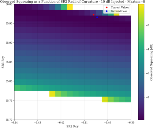
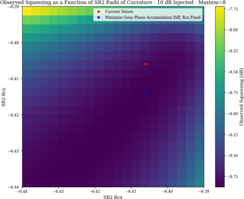
| I've run a few plots of observed squeezing in the LIGO interferometer to fully ensure that the point we have selected is the optimal point for squeezing. Contrary to what I expected, there seems to be much more degenerate "optimal" configurations. While the toroidal case may be near optimal, it seems that the solution we found for a non astigmatic beam is not the only one. I will further explore this space to find more optimal/tolerant positions, which I see evidence of.
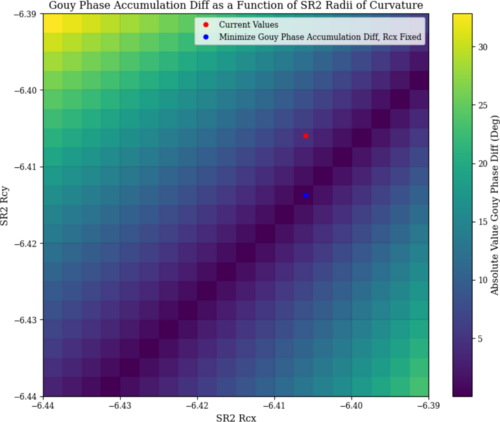
Additionally, as observed squeezing is computational expensive to compute, I found that the difference in round-trip gouy phase accumulation between the x and y planes is a good approximation for an optimal squeezing state, which I believe makes physical sense. This may be helpful to quickly compute other optimal conditions. |
| Attachment 1: Screenshot_2025-08-26_at_12-16-01_LIGO_Project_Log_-_Google_Docs.png
|
|
| Attachment 2: Screenshot_2025-08-26_at_12-16-32_LIGO_Project_Log_-_Google_Docs.png
|
|
| Attachment 3: Screenshot_2025-08-26_at_12-17-26_LIGO_Project_Log_-_Google_Docs.png
|
|
|
548
|
Tue Apr 8 00:17:01 2025 |
Michael | Update | Interferometer Simulations | Squeezing Performance Graphs for Case With and Without Toroidal Mirrors in LIGO |
| I've created some graphs for the frequency dependent observed squeezing level in LIGO for both the nominal case and the case where we include toroidal mirrors, giving some interesting results. https://docs.google.com/presentation/d/1RBr47hNaxFTdGrwys5ZCUEUOgVOVHmZ2B_5EQwY62IY/edit?usp=sharing |
|
129
|
Tue Jun 20 22:14:24 2023 |
Pamella, Cao | Infrastructure | VAC | Short term testing of vacuum heater controller units |
| [Pamella, Cao]
Fuse replacement
- Replace blown 10A fuse in ucontroller outside cleanroom
- Replace 10 A fuse in main power connection slot of the controller unit inside cleanroom
- Pamella wiped down unit outside cleanroom.
- Controller units turned on and temperature setpoint set to be 80 deg C
- Temperature settle in approx. 15 minutes(as recorded by the RTD). No problems with fuses observed
- Recording of pressure gauges (in Torr) :
- Before turning heater on :
- Gauge 1(main chamber): 3.73E-7
- Gauge 2(RGA line): 3.65E-7
- Gauge 3(Pump line): 3.8E-4
- After 15 minutes :
- Gauge 1(main chamber): 7.07E-7
- Gauge 2(RGA line): 6.12E-7
- Gauge 3(Pump line): 3.8E-4
- Reduce setpoint temperature to 60 deg C due to Pinrani gauge (Gauge 3) temperature limit
- Upon returned to lab to reduce temperature (35 minutes after turned on):
- Gauge 1(main chamber): 1.22E-6
- Gauge 2(RGA line): 9.98E-7
- Gauge 3(Pump line): 3.8E-4
- Once temperature has settled to 60 C (approx 20 mins after changing setpoint), pressure readout showed:
- Gauge 1(main chamber): 1.37E-6
- Gauge 2(RGA line): 1.10E-6
- Gauge 3(Pump line): 3.8E-4
- Heater left on for the whole afternoon, pressure readout upon returning to lab at 5:30 pm:
- Gauge 1(main chamber): 3.43E-6
- Gauge 2(RGA line): 2.61E-6
- Gauge 3(Pump line): 3.8E-4
|
|
322
|
Tue Feb 13 04:05:32 2024 |
Michael | Update | Interferometer Simulations | Shoelaces 1 Layout Simulated in GTrace |
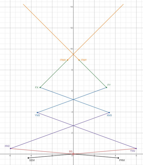
| I've worked on and have completed a first simulation of Cosmic Explorer's Shoelaces 1 layout. This is based off of Pooyan's original work with Gtrace much like the Long Crab 1 layout I worked on last week. This layout will allow me to quickly created the alternate shoelaces layouts. I've included an image of the dxf, and a desmos model for reference. |
| Attachment 1: shoelaces1_dxf.JPG
|

|
| Attachment 2: shoelaces1_desmos.JPG
|
|
|
163
|
Tue Jul 18 16:04:26 2023 |
Pamella | Update | FLIR | Setup FLIR with black wall (black body) |
[Pamella]
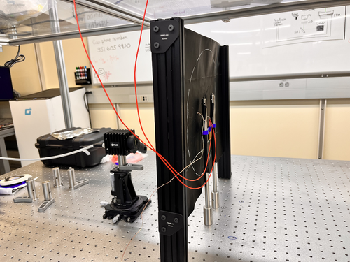
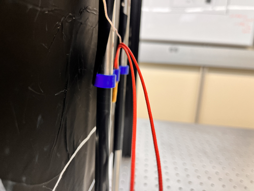
- Today I tried get data the heater with the black screen but doesn't looks possible have just one "energy" point straight to FLIR camera. Tyler and I tried different current and temperatures but keep very bad data. I attached a snap below.
- I attached a photo about the new setup below. The FLIR is in the most close point possible/safety with the heater. The heater is very close to the black wall but is not touch the screen so is safety.
|
| Attachment 1: AcquisitionImage(Jul-18-2023_15_24).jpg
|
.jpg.png)
|
| Attachment 2: IMG_8721.jpeg
|
|
| Attachment 3: IMG_8722.jpeg
|
|
|
505
|
Tue Jan 28 13:30:46 2025 |
shane | Update | CDS | Serial comms testing update |
| Attempted to communicate with the smaller vac pump (TwissTor 74) via Agilent software today. Was able to communicate with the pump via python serial connection code as usual, with no issues. When using the manufacturer software though, it was unable to 'locate' the pump and failed to connect to it. So manufacturer software works for the big (older) pump, but not the smaller, newer one. Unclear if this is somehow related to the fact that using the manufacturer software for the bigger pump involved manually connecting its controller to spica with a db9, and there was no obvious way to do that for the smaller pump's controller. |
|
419
|
Fri Aug 2 13:50:22 2024 |
Shane | Update | CDS | Serial Comm. Test (Agilent Turbo Pump) |
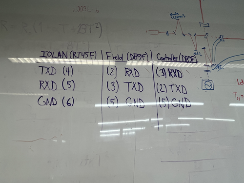
| Did a brief communication test with the agilent turbo pump today, to see if we could get serial communications up and running for it. Used a simplified python script with sockets package to establish a connection and send a simple command to query the pump's operational status. The connection was successful, and had no issues establishing. The command also sent successfully, and received a response. The response didn't make sense, though, as all the possible statuses correspond to integers 0-7, and this test returned the integer 15. Need to troubleshoot some more to figure out why it's returning nonsense values. Possible match-up issue with the way the information is being encoded on each end? At the very least, connection and command sending are both working fine, and this showed that the pin-out connections we were assuming (image attached) are correct for basic connection to work. |
| Attachment 1: pinouts.jpeg
|
|
|
656
|
Thu Oct 23 11:09:16 2025 |
Xuesi Ma | Update | Measuring Noise in Interferometer | Scatter Noise Model |
DetChar meeting presentation |
|
358
|
Mon Apr 8 14:43:29 2024 |
Pooyan | Update | Interferometer Simulations | SIS update single and coupled cavities |
| [Pooyan, Cynthia]
Attached is a brief recap PDF file. A video file showing separate HOMs plots for the cavity scan with ETM08 surface map is also attached.
The codes are available at https://git.ligo.org/uc_riverside/hom-rh/-/tree/main/SIS |
| Attachment 1: IFOSim_SIS__update_4_8_24.pdf
|

|
| Attachment 2: Screen_Recording_2024-03-31_at_2.46.29_AM.mov
|
|
381
|
Mon Jun 24 14:28:51 2024 |
Cynthia | Update | Interferometer Simulations | SIS cavity with thermal effect |
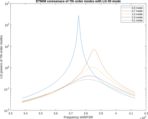
| tried to run a cavity scan with thermal deformation and ring heater for ITM04 ETM08 (aLIGO mirrors). Not sure about the accuracy of the graph as there is some commands that still need to verified. |
| Attachment 1: ETM08thermal.png
|
|
|
662
|
Thu Nov 20 12:40:47 2025 |
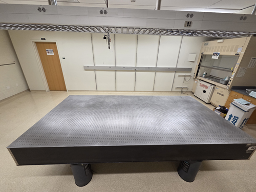
Xuesi Ma | Infrastructure | General | Room 1125 Optical Table |
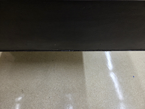
Cleaned off the tapes on the optical table with acetone. |
| Attachment 1: 1651.jpg
|
|
| Attachment 2: 1650.jpg
|
|
|
444
|
Mon Sep 23 08:29:49 2024 |
Luke | Update | Interferometer Simulations | Ringheater update |
|
Ringheater Update
If the link does not work here is the file. |
| Attachment 1: 20240923_Update.pptx
|
|
513
|
Sun Feb 16 16:45:18 2025 |
Luke | Update | General | Ringheater position optimization |
Over the last couple weeks I have been working on finding the optimal position of the ringheater's thermal profile.
Today I would like to give an update of where I am at and my next steps.
Using the python COMSOL interface I have been able to run and save deformation data sweeping through a great deal of potential combinations of widths and positions.
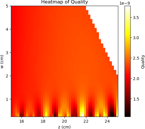
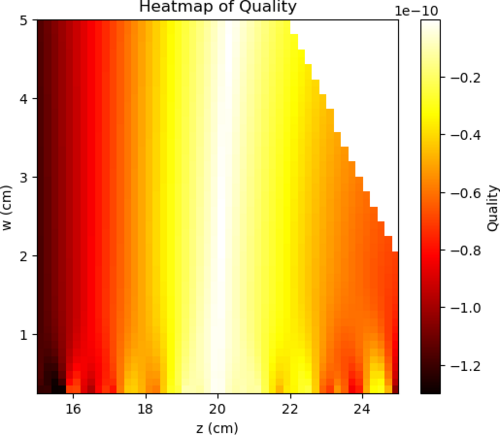
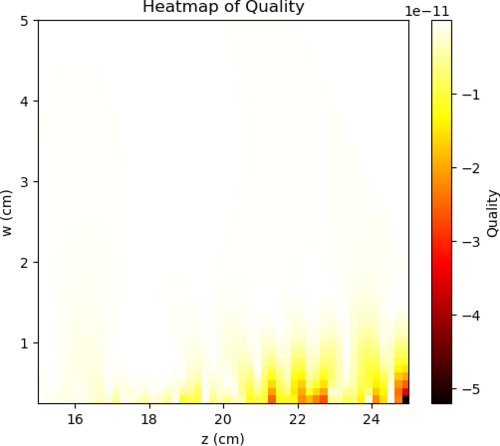
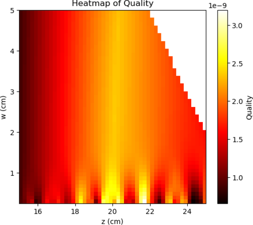
I then calculated their zernike coefficients and using a very simple "quality" function (02 - (40)*10 - (4-4)*10), where 02 stands for the zernike mode of quadratic deformation, I was able to generate a heat map of comparing the "quality" verses the width and position used.
Seen below are four plots. The first is simply the 02 coefficient of the decomposition followed by the negative of 40 and 4-4 then the "quality."
This 'quality' function was an arbitrary choice on my part. I believe that my next step would either be defining a more useful function or using finesse to model the actual effects of this surface deformation. |
| Attachment 1: 02.png
|
|
| Attachment 2: _40.png
|
|
| Attachment 3: _4-4.png
|
|
| Attachment 4: 02_40_4-4.png
|
|
|
423
|
Mon Aug 12 16:35:30 2024 |
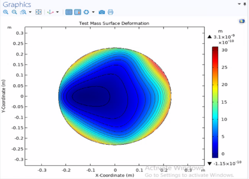
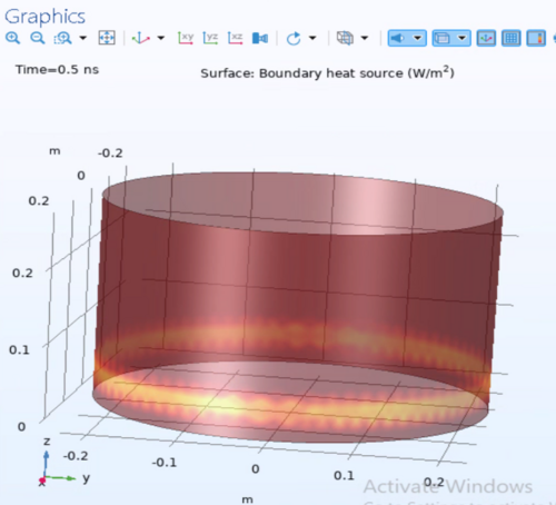
Luke | Update | | Ringheater modeling Update |
|
| Attachment 1: HR_surface_deformation.png
|
|
| Attachment 2: Irradiation_pattern_input.png
|
|
| Attachment 3: HR_surface_deformation_other.png
|
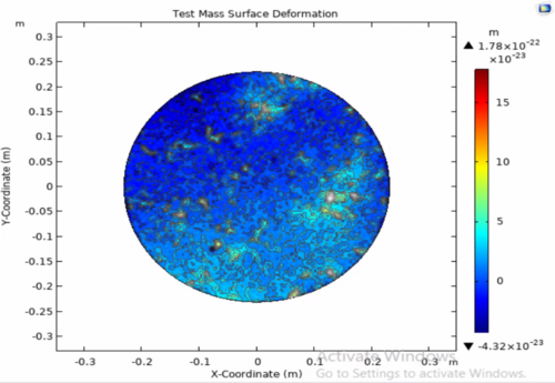
|
|
452
|
Wed Oct 2 12:05:42 2024 |
Luke | Update | | Ringheater modeling Update |
Power point slides |
|
502
|
Sat Jan 25 18:19:39 2025 |
Luke | Update | General | Ringheater modeling Update |
Here is a quick update on some of the things I have been working on regarding my project. |
|
521
|
Sun Feb 23 16:00:07 2025 |
Luke | Update | Scripts/Programs | Ringheater modeling Update |
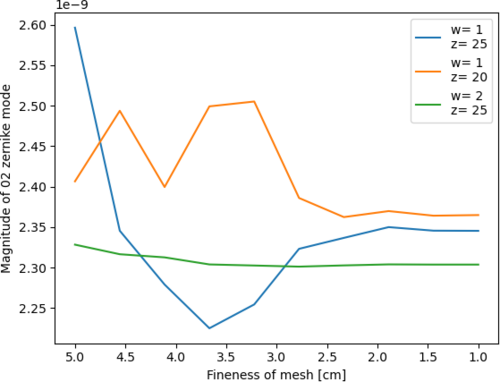
These are some plots:
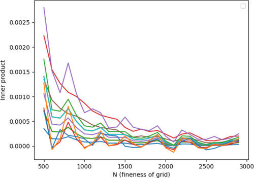
The first shows the convergence of the 02 mode reducing the size of the mesh. The second shows the the numerical error of the zernike.
The first is found by sweeping a parameter that changes the size of the mesh. The HR surface was set to half a cm for all values.
The second by taking the inner product of a zernike mode with its self and calculating its deviation from pi for varying fineness of the mesh. |
| Attachment 1: mesh_convergence.png
|
|
| Attachment 2: numerical_error_in_innerproduct_of_zernike_basis_elemets.png
|
|
|
569
|
Sun May 4 18:17:45 2025 |
Luke | Update | Scripts/Programs | Ringheater modeling Update |
Slides
I have changed some properties of the thermal model and am re-running the thermal sweeping
I have also been messing around with making a logo |
|
584
|
Mon Jun 2 09:45:06 2025 |
Luke | Update | Scripts/Programs | Ringheater modeling Update |
Slides
I have added some slides to my meeting updates. The updates include: my choice in position and width, some figures I have added to my write up, and what I think my immediate steps are to wrap up.
I have also made a new FROSTI model that conducts its raytracing in real time. Something that was severely lacking in the previous model. |
|
430
|
Tue Aug 27 18:37:40 2024 |
Luke | Update | Interferometer Simulations | Ringheater model update |
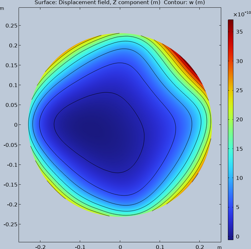
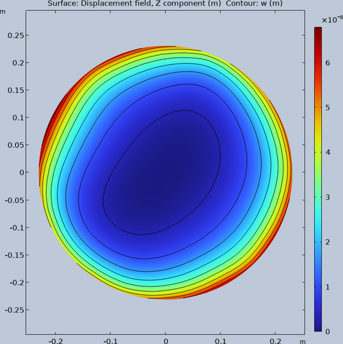
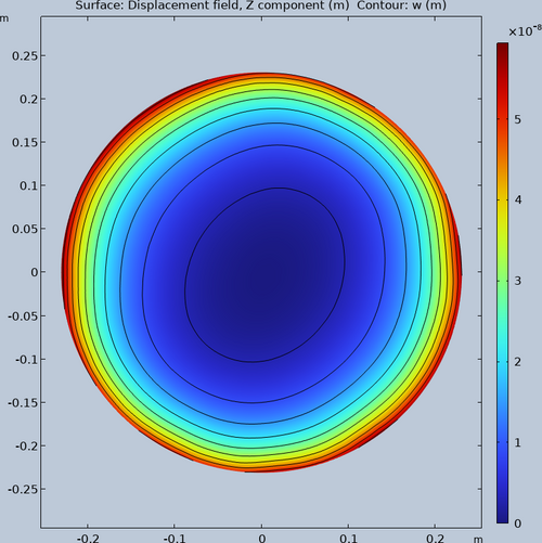
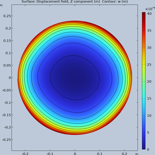
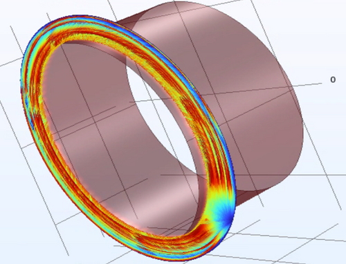
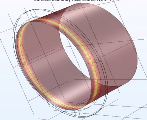
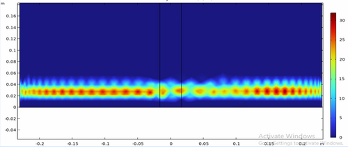
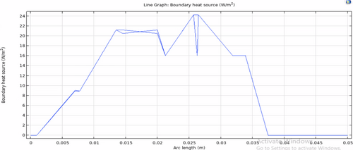
| Updated the model to produce a more circular deformation in the HR surface. The first three attachments are from irradiance patterns gotten from ray tracing. The last is from a pre-defined irradiance pattern. |
| Attachment 1: Initial_1W.png
|
|
| Attachment 2: Increased_rays_100W.png
|
|
| Attachment 3: Increased_rays_more_100W.png
|
|
| Attachment 4: Initial_100W.png
|
|
|
541
|
Sun Mar 23 15:39:06 2025 |
Luke Johnson | Update | Scripts/Programs | Ringheater Location optimization |
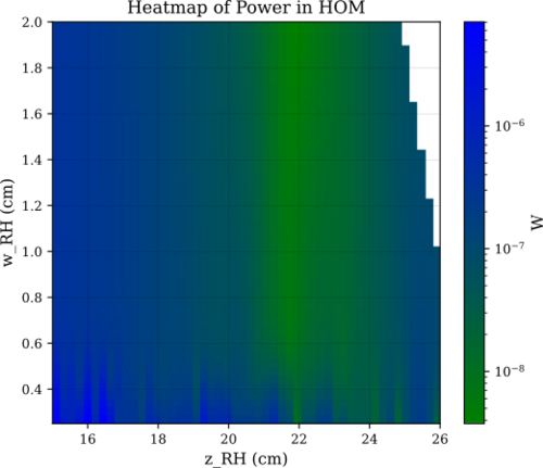
| Attached are some plots that show a new parameter sweep with a finer mesh then before. I have also been able to get a heatmap of power of HOMs in a very simple finesse model. |
| Attachment 1: _4-4.png
|

|
| Attachment 2: _40.png
|

|
| Attachment 3: 02.png
|

|
| Attachment 4: HOM_power.svg
|
|
|
439
|
Mon Sep 16 07:28:16 2024 |
Luke | Update | Interferometer Simulations | Ring heater update |
|
| Attachment 1: 20240916_Ringheater_updates.pptx
|
|
403
|
Sat Jul 13 15:09:04 2024 |
Luke | Update | General | Ring heater COMSL model update |
After the feedback from last meeting and Liu's help narrowing down what I should do to improve the model. I made some changes: First with Liu's help I made the proportions of the test mass and ring heater much more reasonable and parametrized by constants. Second from Cao's paper "FROSTI Nonimaging Reflector Design" Liu showed me what I should do to define the elliptical mirrors. Third during Friday's modeling/programming meeting walked me through getting the different irradiance plots to work. |
| Attachment 1: image_2024-07-13_150654436.png
|
|
| Attachment 2: image_2024-07-13_150704735.png
|
|
| Attachment 3: image_2024-07-13_150716079.png
|
|
| Attachment 4: image_2024-07-13_150726593.png
|
|
|
342
|
Tue Feb 27 03:26:28 2024 |
Michael | Update | Interferometer Simulations | Reverse aLIGO Layout Created in Gtrace |
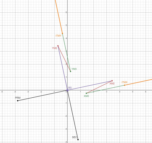
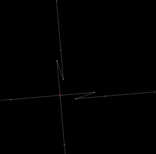
| I've created the simulation for reverse aLIGO layout in gtrace. Attached are the desmos model and the output dxf file. From here Pooyan and I plan to create a brief report of our progress to the CE optical design group. |
| Attachment 1: reverse_aligo_desmos.JPG
|
|
| Attachment 2: reverse_aligo_dxf.JPG
|
|
|
344
|
Wed Feb 28 12:02:08 2024 |
Tyler | Update | General | Resistors for Heater Elements Update |
| Power Res (Ohm) RTD Res (Ohm)
Heater 1= 72.8; 80.6
Heater 2= 69.5; 80.8
Heater 3= 70; 83.2
Heater 4= 70.6; 78.7
Heater 5= 69.9; 80.6
Heater 6= 71.1; 78.2
Heater 7= 68.5; 76.8
Heater 8= 70.1; 82.8
| Quote: |
| Power Res (Ohm) RTD Res (Ohm)
Heater 1= 73.6; 81.8
Heater 2= 70.4; 82.1
Heater 3= 71; 84.5
Heater 4= 71.5; 80
Heater 5= 70.5; 81.7
Heater 6= 72; 79.4
Heater 7= 69.2; 78.2
Heater 8= 71.1; 84.2 |
|
|
307
|
Wed Jan 17 15:47:49 2024 |
Aiden | Update | General | Resistors for Heater Elements |
| Power Res (Ohm) RTD Res (Ohm)
Heater 1= 73.6; 81.8
Heater 2= 70.4; 82.1
Heater 3= 71; 84.5
Heater 4= 71.5; 80
Heater 5= 70.5; 81.7
Heater 6= 72; 79.4
Heater 7= 69.2; 78.2
Heater 8= 71.1; 84.2 |
|
517
|
Tue Feb 18 11:19:13 2025 |
Luke | Configuration | VAC | Repositioning of the lid's temperature probe |
| Before the recent bake I slightly repositioned the temperature probe on the lid from beside the heater tape to under the heater tape. This was done to better know and control the temperatures of the chamber while baking. It has appeared to work with the temperatures being held very close to the 120C target. |
|
170
|
Mon Jul 24 14:55:53 2023 |
Jon | Update | VAC | Removed extension power cable |
| I removed the extension cable that was powering the leftmost heater controller, since there is no bake currently happening. It is currently powering the LED over the electronics bench, and can be removed if needed. I will be ordering more extension cords to permanentize our setups. |
|
466
|
Tue Oct 29 16:37:35 2024 |
Tyler | Update | Electronics | Red Pitaya OS Update |
The Red Pitaya ecosystem has been upgraded to OS 2.00-35, with a key feature being greater freedom in adjusting the sampling frequency for signal analysis. Before, decimation factors could only be applied if they were a power of 2 (i.e 2,4,8,16,...) up to 65536. Now, the factors can be any power of two up to 16, and any whole number greater than 16 up to 65536. Further information can be found here. |
|
624
|
Mon Aug 11 22:19:50 2025 |
Christina | Update | TCS | Red Pitaya Data Streaming |
[Ma, Tyler, Christina]
This past week, we were able to set up the data streaming for continuous acquisition to the PCs, and can conduct the initial tests now. We were able to do this by:
- Installing the correct OS ecosystems to each Red Pitaya
- Installing the terminal streaming client
- Debugging formatting and file saving issues by saving the data in a TDMS file on the host PC.
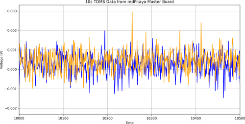
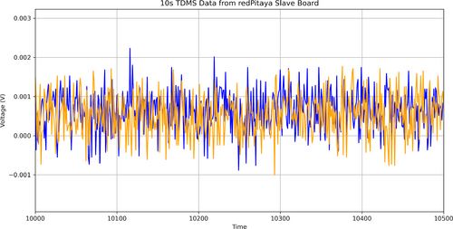
We have started streaming the ADC data on Monday from both boards for 2 days, which are currently in the clean room. Below are the ADC tests we performed before starting the 2-day run. (Time in ms) |
| Attachment 1: 3.png
|
|
| Attachment 2: 3-1.png
|
|
|
78
|
Tue Apr 25 11:56:37 2023 |
Jon | Update | VLC Electronics | Red Pataya has arrived |
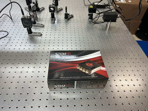
| The Red Pataya 125-14 starter kit that we ordered for locking the 532 nm cavity has arrived. I left it laying on the optical table near the laser. |
| Attachment 1: Red_Pataya.jpg
|
|
|
366
|
Mon May 13 13:03:41 2024 |
Tyler | Update | FLIR | Readout Code Updates |
| [Tyler]
Some changes have been made to the FLIR readout code to help improve its functionality:
- More accurate temperature readings than before due to updates in the calculation procedure. A bug was causing one of the parameters to not update correctly; this is now fixed.
- Saved data now stored in HDF5 files rather than CSV.
- User can now enable automatic data storage by specifying a collection interval (in minutes). The choice of manually saving data is still present if desired.
Below is an image of the graphical interface. This is an old screenshot. Visually, there is no difference between the older and newer version. The differences come from the list above, which help the user more reliably measure and store data for later analysis.
|
| Attachment 1: AcquisitionImage(Jul-18-2023_15_24).jpg.png
|
.jpg.png.png)
|
|
313
|
Fri Feb 2 16:56:56 2024 |
Jon | Update | CDS | RTS model implemented for FROSTI RTD readouts |
Summary
Today I finished implementing an RTS model to read out the integrated FROSTI RTDs (temperature sensors) via the CyMAC. The model is named "MSC" and is located at cymac:/opt/rtcds/usercode/models/c1msc.mdl. We successfully tested it with the heater elements operating in vacuum at low power (12 VDC), finding them to reach an average steady-state temperature of 160 C.
From the cymac host, the MEDM control screen can be accessed with the terminal command "sitemap" (from any directory).
Measurement Technique
Each FROSTI heater element [299] contains an internal two-wire RTD placed near the front emitting surface, which enables the temperature of the blackbody emitter to be directly monitored. From the measured temperature and the emissivity of the uncoated aluminum nitride surface (known to be ~1 in the IR), the radiated source-plane power can also be estimated.
The resistance of each RTD is measured via a ratiometric technique. The RTDs are powered in series with a 1 kΩ reference resistor located inside the readout chassis [305], whose temperature is not changing. The signal is obtained by taking the ratio of the voltage difference across each individual RTD to the voltage difference across the reference resisitor. The advantage of this technique is that the ratio of the voltage differences is insensitive to changes in the current through the resistors (since they are all in series; see [271] for wiring diagram).
Implementation Detail
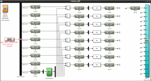
The signal flow is shown in Attachment 1. The eight RTD signals enter through ADC channels 0-7, along with the reference resistor signal on channel 8. The first set of filter modules apply a calibration gain to convert the signals from raw ADU counts to units of input-referred voltage. The ratio of each RTD signal to the reference resistor signal is then taken. The second set of filter modules multiply the voltage-difference ratios by the resistance of the reference resistor, 1 kΩ ± 0.01%, to obtain the RTD resistances in physical units of ohms.
Finally, a freeform math module is used to invert the quadratic relation between each RTD's resistance and temperature. The final signals passed to the third set of filter modules are the RTD temperatures in physical units of degrees C. The temperatures of the tungsten RTDs are estimated assuming TCR coefficients of A=0.0030 C-1 (±10%) and B=1.003E-6 C-2, which were provided by the manufacturer.
One DAC channel is used to provide the excitation voltage for the RTD measurement, which is visible on the far right of the control screen. At its maximum output voltage of +10 V, the DAC can drive a maximum current of 10 mA. |
| Attachment 1: sitemap_screen.png
|
|
|
305
|
Tue Jan 16 12:20:21 2024 |
Tyler | Configuration | Electronics | RTD Readout Chassis Update 2 |
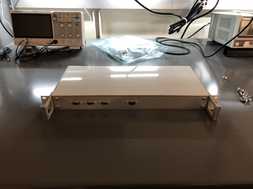
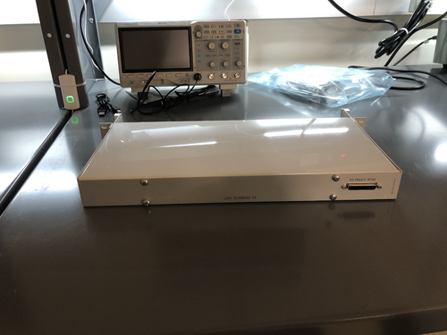
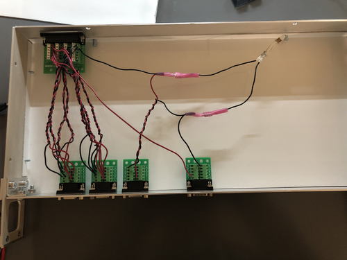
I performed another continuity test on the RTD chassis wiring, and everything seems to be set up correctly. The chassis should be ready for installation.
| Quote: |
Below is the current state of the RTD readout chassis wiring. Initial continuity tests seem good, will run through one more time to confirm.
| Quote: |
The custom front and rear panels for the RTD readout chassis arrived last Friday. I installed them in the chassis frame to check their fit. They fit very well, so all that now remains is to complete the internal wiring and test the connections.
The chassis panel designs are archived to LIGO-D2300452 and LIGO-D2300453.
| Quote: |
|
Below are a basic diagram of what the RTD measurement circuit logically looks like and an example schematic of the actual wiring. The schematic wiring will be placed internally into a chassis, connected to the RTDs via DB25 cable.
Note: The DB25 Breakout Board connector is Female, not Male. |
|
|
|
| Attachment 1: IMG_8146.jpg
|
|
| Attachment 2: IMG_8147.jpg
|
|
|
300
|
Tue Jan 9 12:08:59 2024 |
Tyler | Configuration | Electronics | RTD Readout Chassis Update |
Below is the current state of the RTD readout chassis wiring. Initial continuity tests seem good, will run through one more time to confirm.
| Quote: |
The custom front and rear panels for the RTD readout chassis arrived last Friday. I installed them in the chassis frame to check their fit. They fit very well, so all that now remains is to complete the internal wiring and test the connections.
The chassis panel designs are archived to LIGO-D2300452 and LIGO-D2300453.
| Quote: |
|
Below are a basic diagram of what the RTD measurement circuit logically looks like and an example schematic of the actual wiring. The schematic wiring will be placed internally into a chassis, connected to the RTDs via DB25 cable.
Note: The DB25 Breakout Board connector is Female, not Male. |
|
|
| Attachment 1: IMG_8105.jpg
|
|
|
364
|
Thu May 2 22:43:36 2024 |
Tyler | Update | Electronics | RTD Readout Chassis Redesign |
| [Tyler, Jon]
Today the FROSTI RTD readout chassis underwent a redesign:
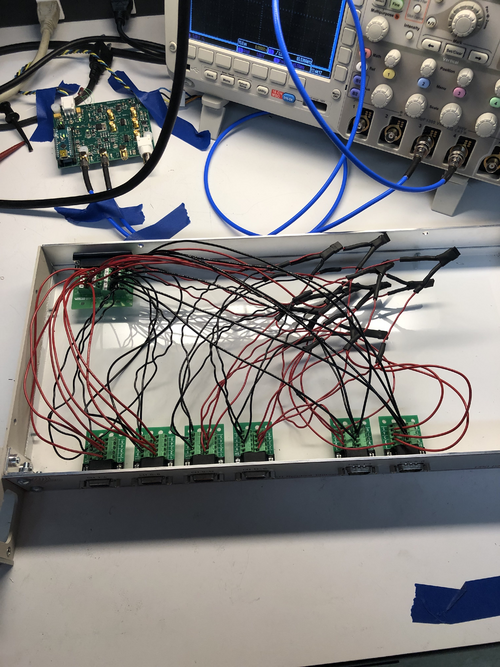
Instead of the original ratiometric method, which involved wiring the FROSTI RTDs in series, each element is individually powered by separate excitations. Each element additionally possesses its own reference resistor of 100 Ohm. Now, if an RTD experiences an electrical short, it should not affect the measurements of the others in sequence, as it had with the original design.
|
| Attachment 1: IMG_9013.jpg
|
|
|
298
|
Fri Dec 29 16:02:27 2023 |
Jon | Configuration | Electronics | RTD Readout Chassis |
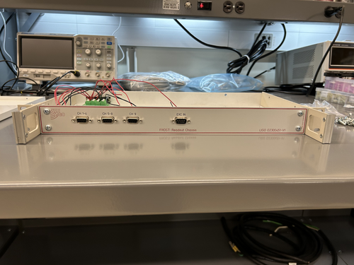
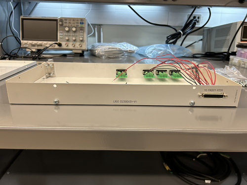
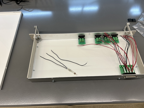
The custom front and rear panels for the RTD readout chassis arrived last Friday. I installed them in the chassis frame to check their fit. They fit very well, so all that now remains is to complete the internal wiring and test the connections.
The chassis panel designs are archived to LIGO-D2300452 and LIGO-D2300453.
| Quote: |
|
Below are a basic diagram of what the RTD measurement circuit logically looks like and an example schematic of the actual wiring. The schematic wiring will be placed internally into a chassis, connected to the RTDs via DB25 cable.
Note: The DB25 Breakout Board connector is Female, not Male. |
|
| Attachment 1: front.jpeg
|
|
| Attachment 2: rear.jpeg
|
|
| Attachment 3: overhead.jpeg
|
|
|
351
|
Thu Mar 21 16:56:42 2024 |
Tyler | Update | DAQ | RTD Parameter Calibration |
| [Jon,Tyler]
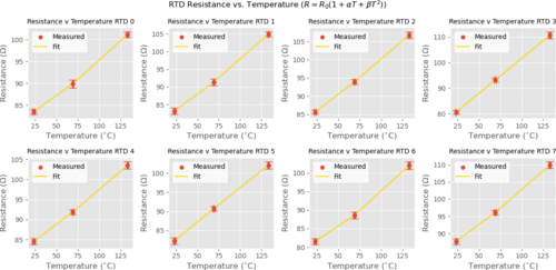
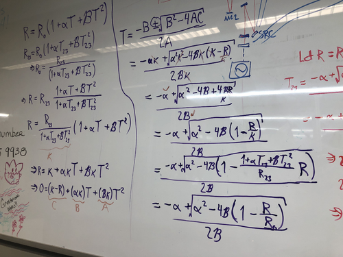
We noticed that the RTD temperature readings given on the Cymac were off, and traced the issue to miscalibration in the relationship between the resistance and temperature of each RTD (Callendar-Van Dusen eqn). Below is the table of values inferred from independent measurements of temperature and resistance to rectify this problem. This data was then fitted to better determine the coefficients present in the temperature-resistance relation:
R_0 (ohm) Alpha Beta
RTD 0 80.8674 0.001315 4.273e-6
RTD 1 79.5704 0.001887 3.7873e-6
RTD 2 81.7334 0.002014 2.1724e-6
RTD 3 74.3060 0.003677 3.6022e-8
RTD 4 81.1350 0.001761 2.3598e-6
RTD 5 77.9610 0.002423 -7.5192e-7
RTD 6 78.7980 0.001373 6.2909e-6
RTD 7 83.8616 0.001890 3.3529e-6 |
| Attachment 1: RTD_Calib-2.png
|
|
| Attachment 2: IMG_8569.jpg
|
|
|
354
|
Mon Mar 25 10:55:33 2024 |
Tyler | Update | DAQ | RTD Parameter Calibration |
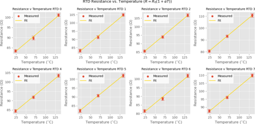
| Refitted RTD calibration, neglecting quadratic term:
R_0 (ohm) Alpha (1/C)
RTD 0 79.3962 0.002031
RTD 1 78.2874 0.002530
RTD 2 80.9775 0.002381
RTD 3 74.2947 0.003684
RTD 4 80.3199 0.002157
RTD 5 78.2106 0.002297
RTD 6 76.6825 0.002438
RTD 7 82.6645 0.002458
Measurements taken can be found here. An uncertainty of 1 C was assumed for temperature.
| Quote: |
| [Jon,Tyler]
We noticed that the RTD temperature readings given on the Cymac were off, and traced the issue to miscalibration in the relationship between the resistance and temperature of each RTD (Callendar-Van Dusen eqn). Below is the table of values inferred from independent measurements of temperature and resistance to rectify this problem. This data was then fitted to better determine the coefficients present in the temperature-resistance relation:
R_0 (ohm) Alpha Beta
RTD 0 80.8674 0.001315 4.273e-6
RTD 1 79.5704 0.001887 3.7873e-6
RTD 2 81.7334 0.002014 2.1724e-6
RTD 3 74.3060 0.003677 3.6022e-8
RTD 4 81.1350 0.001761 2.3598e-6
RTD 5 77.9610 0.002423 -7.5192e-7
RTD 6 78.7980 0.001373 6.2909e-6
RTD 7 83.8616 0.001890 3.3529e-6 |
|
| Attachment 1: RTD_Calib_nobeta.png
|
|
|
355
|
Tue Mar 26 13:51:56 2024 |
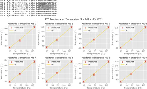
Tyler | Update | DAQ | RTD Parameter Calibration |
Another re-fit, but this time the quadratic coefficient (beta) is set to 1.003e-6:
R_0 (ohm) Alpha (1/C)
RTD 0 79.7386 0.001863
RTD 1 78.6248 0.002359
RTD 2 81.3254 0.002211
RTD 3 74.6127 0.003509
RTD 4 80.6652 0.001988
RTD 5 78.5450 0.002127
RTD 6 77.0144 0.002268
RTD 7 83.0204 0.002288
| Quote: |
| Refitted RTD calibration, neglecting quadratic term:
R_0 (ohm) Alpha (1/C)
RTD 0 79.3962 0.002031
RTD 1 78.2874 0.002530
RTD 2 80.9775 0.002381
RTD 3 74.2947 0.003684
RTD 4 80.3199 0.002157
RTD 5 78.2106 0.002297
RTD 6 76.6825 0.002438
RTD 7 82.6645 0.002458
Measurements taken can be found here. An uncertainty of 1 C was assumed for temperature.
| Quote: |
| [Jon,Tyler]
We noticed that the RTD temperature readings given on the Cymac were off, and traced the issue to miscalibration in the relationship between the resistance and temperature of each RTD (Callendar-Van Dusen eqn). Below is the table of values inferred from independent measurements of temperature and resistance to rectify this problem. This data was then fitted to better determine the coefficients present in the temperature-resistance relation:
R_0 (ohm) Alpha Beta
RTD 0 80.8674 0.001315 4.273e-6
RTD 1 79.5704 0.001887 3.7873e-6
RTD 2 81.7334 0.002014 2.1724e-6
RTD 3 74.3060 0.003677 3.6022e-8
RTD 4 81.1350 0.001761 2.3598e-6
RTD 5 77.9610 0.002423 -7.5192e-7
RTD 6 78.7980 0.001373 6.2909e-6
RTD 7 83.8616 0.001890 3.3529e-6 |
|
|
| Attachment 1: Screenshot_2024-03-26_at_1.23.27_PM.png
|
|
|
416
|
Mon Jul 29 13:39:16 2024 |
Tyler | Update | DAQ | RTD Parameter Calibration |
| [Tyler]
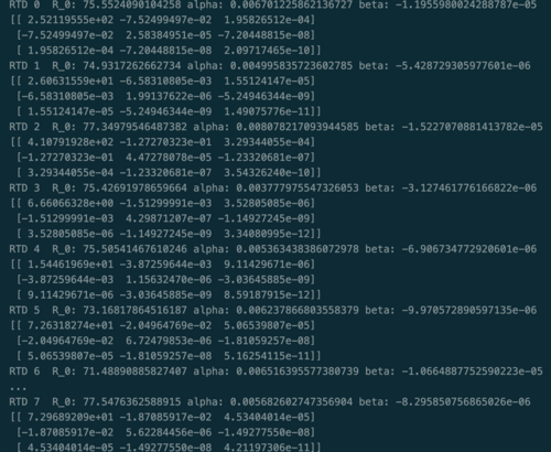
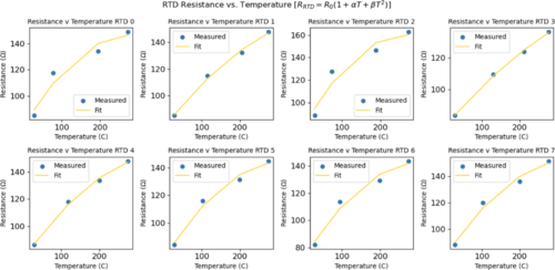
Using the data taken during the FROSTI testing at Caltech, I attempted to find a better calibration of the RTD sensors, given our past issues with inaccurate readings. The fit parameters, alpha and beta, are still all different from the initial values given to us by Fralock (alpha = .003, beta = 1.003e-6, R_0 was not given), but the true values will differ based on factors such as part geometry.
| Quote: |
| Refitted RTD calibration, neglecting quadratic term:
R_0 (ohm) Alpha (1/C)
RTD 0 79.3962 0.002031
RTD 1 78.2874 0.002530
RTD 2 80.9775 0.002381
RTD 3 74.2947 0.003684
RTD 4 80.3199 0.002157
RTD 5 78.2106 0.002297
RTD 6 76.6825 0.002438
RTD 7 82.6645 0.002458
Measurements taken can be found here. An uncertainty of 1 C was assumed for temperature.
| Quote: |
| [Jon,Tyler]
We noticed that the RTD temperature readings given on the Cymac were off, and traced the issue to miscalibration in the relationship between the resistance and temperature of each RTD (Callendar-Van Dusen eqn). Below is the table of values inferred from independent measurements of temperature and resistance to rectify this problem. This data was then fitted to better determine the coefficients present in the temperature-resistance relation:
R_0 (ohm) Alpha Beta
RTD 0 80.8674 0.001315 4.273e-6
RTD 1 79.5704 0.001887 3.7873e-6
RTD 2 81.7334 0.002014 2.1724e-6
RTD 3 74.3060 0.003677 3.6022e-8
RTD 4 81.1350 0.001761 2.3598e-6
RTD 5 77.9610 0.002423 -7.5192e-7
RTD 6 78.7980 0.001373 6.2909e-6
RTD 7 83.8616 0.001890 3.3529e-6 |
|
|
| Attachment 1: RTD_Recal_params.png
|
|
| Attachment 2: RTD_recal_plots_fin.png
|
|
|
271
|
Mon Nov 20 10:10:50 2023 |
Tyler | Configuration | Electronics | RTD Logic/Schematic Diagrams |
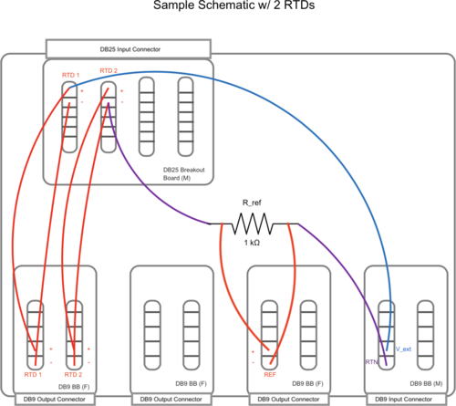
Below are a basic diagram of what the RTD measurement circuit logically looks like and an example schematic of the actual wiring. The schematic wiring will be placed internally into a chassis, connected to the RTDs via DB25 cable.
Note: The DB25 Breakout Board connector is Female, not Male. |
| Attachment 1: FIN_RTD_circuit.png
|

|
| Attachment 2: Sample_Circuit_Schematic.png
|
|
|
310
|
Tue Jan 23 12:17:41 2024 |
Tyler | Update | Electronics | RTD Chassis |
After updating the wiring in the RTD Chassis, a signal is now seen at each ADC input. However, there seems to be a discrepancy between the voltages I measured out with the multimeter (see below). Next steps include:
- Finish final debugging
- Calibrate ADC inputs with known voltage source (likely to use DAC).
Voltage Readings:
RTD 1: 0.576 V
RTD 2: 0.578 V
RTD 3: 0.598 V
RTD 4: 0.563 V
RTD 5: 0.477 V
RTD 6: 0.463 V
RTD 7: 0.456 V
RTD 8: 0.491 V
Reference Resistor: 5.463 V
Total Voltage: 9.665 V |
| Attachment 1: rtd_updated_circuitry.jpg
|
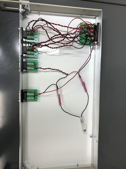
|
|
311
|
Tue Jan 30 11:36:19 2024 |
Tyler | Update | Electronics | RTD Chassis |
| Quote: |
After updating the wiring in the RTD Chassis, a signal is now seen at each ADC input. However, there seems to be a discrepancy between the voltages I measured out with the multimeter (see below). Next steps include:
- Finish final debugging
- Calibrate ADC inputs with known voltage source (likely to use DAC).
Voltage Readings:
RTD 1: 0.576 V
RTD 2: 0.578 V
RTD 3: 0.598 V
RTD 4: 0.563 V
RTD 5: 0.477 V
RTD 6: 0.463 V
RTD 7: 0.456 V
RTD 8: 0.491 V
Reference Resistor: 5.463 V
Total Voltage: 9.665 V |
After further modification of the RTD readout chassis (i.e. adding resistors, placing reference resistor in front of RTDs), here are the following direct measurements:
RTD 1: 0.484 V
RTD 2: 0.486 V
RTD 3: 0.503 V
RTD 4: 0.474 V
RTD 5: 0.495 V
RTD 6: 0.483 V
RTD 7: 0.476 V
RTD 8: 0.510 V
Reference: 5.847 V
Here are the Cymac signal readings:
RTD 1: 74
RTD 2: 67
RTD 3: 73
RTD 4: 45
RTD 5: 82
RTD 6: 75
RTD 7: 70
RTD 8: 71
Reference: 884
The one (possible) discrepancy here is the readout for RTD 4 via Cymac, since it's signal reading is ~30 counts lower than the others. I do not believe this is a wiring issue due to the direct measurements taken. |
|
264
|
Mon Nov 13 11:07:50 2023 |
Tyler | Update | VAC | RTD Analysis |
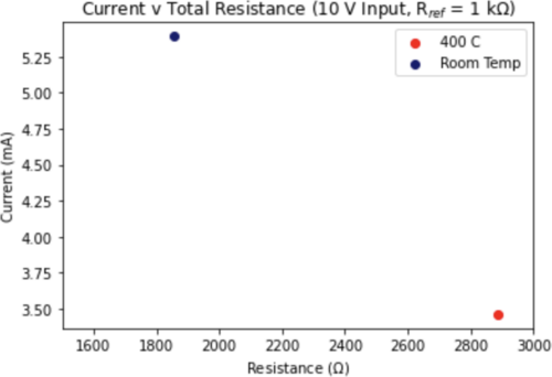
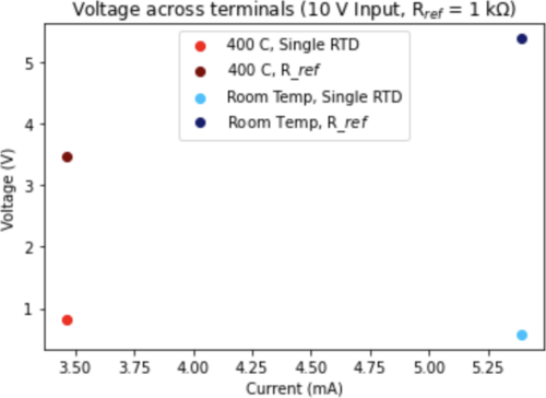
After initial analysis from last week on a single RTD, I then extended to looking at all 8 in series with R_ref (set to 1 kOhm). Shown below are the edge cases for the setup:
- RTDs are all at ambient lab temperature. This would correspond to a minimum resistance value.
- RTDs all read out 400 C. This gives the maximum resistance value.
The results show that indeed only a few mA of current is drawn even at room temperature (a little above 5.5 mA), and this will continue to decrease with increasing temperature. The voltage across a single terminal, at a maximum, is only about 5.4 V. |
| Attachment 1: Screenshot_2023-11-13_at_11.05.45_AM.png
|
|
| Attachment 2: Screenshot_2023-11-13_at_11.06.04_AM.png
|
|