ligo-ex ligo-ds
  Richardson Lab Experimental Log, Page 11 of 11  Not logged in ELOG logo
ID Date Author Typedown Category Subject
  98   Sun May 14 15:50:48 2023 CaoInfrastructureComputersHigh resolution display of logrus machine
[Cao]

The display resolution of the logrus has been 1064x768 and has been the only option, which is not great. While remote access to logrus using rdesktop allows rendering a virtual display of user's chosen resolution, it is not fast when using graphic-intensive program. NoMachine allows user to take over and control the machine remotely and thus appears as the same machine. However, NoMachine cannot render a virtual display like rdesktop. This has been limiting the resolution of using logrus via NoMachine.

On Friday, I found that even though we had NVIDIA Quadro P600 graphic card installed, we were not actually using it. The monitor has been connecting to the the integrated VGA display connector. This uses Microsoft Basic Display Adapter which limits the the resolution. Today I got a HDMI to Mini-display cable to connector the monitor to the Nvidia graphic card. Then in Display settings, go to Graphic settings, then enable Hardware-accelerated GPU scheduling. After restarting the machine, the machine recognised the Display 2using the Nvidia Quadro P600. In multiple displays field, selected "Show only on 2" and remove the VGA connection to the monitor. Logrus is now set at Nvidia Qadro P600 native display resolution of 1920x1080. This is now also the display resolution in NoMachine.

  122   Tue Jun 13 21:08:46 2023 PamellaInfrastructureVACHeater system - Installation
[Pamella, Cao and Jon]
    Heating system installation
  • Today we started installing the equipments for the heating system.
  • First: Started installing the heating cable on the top lid and covered it with aluminum tape.
  • Second: Started installing the insulation cover on top of the chamber lid.
  • Third:Started installing the heating cable from under the vacuum chamber and covered with aluminum tape.
  • Forth: Started installing the insulation cover under the vacuum chamber
  • Note: The under part of the chamber vacuum was very difficult to cover, so we spent a little time on it and we couldn't finish the whole installation today. So tomorrow we should be able to keep doing the installation.
Attachment 1: IMG_7563.jpeg
IMG_7563.jpeg
Attachment 2: IMG_7561.jpeg
IMG_7561.jpeg
  129   Tue Jun 20 22:14:24 2023 Pamella, CaoInfrastructureVACShort term testing of vacuum heater controller units
[Pamella, Cao]

Fuse replacement

  • Replace blown 10A fuse in ucontroller outside cleanroom
  • Replace 10 A fuse in main power connection slot of the controller unit inside cleanroom
  • Pamella wiped down unit outside cleanroom.
  • Controller units turned on and temperature setpoint set to be 80 deg C
  • Temperature settle in approx. 15 minutes(as recorded by the RTD). No problems with fuses observed
  • Recording of pressure gauges (in Torr) :
    1. Before turning heater on :
      1. Gauge 1(main chamber): 3.73E-7
      2. Gauge 2(RGA line): 3.65E-7
      3. Gauge 3(Pump line): 3.8E-4
    2. After 15 minutes :
      1. Gauge 1(main chamber): 7.07E-7
      2. Gauge 2(RGA line): 6.12E-7
      3. Gauge 3(Pump line): 3.8E-4
  • Reduce setpoint temperature to 60 deg C due to Pinrani gauge (Gauge 3) temperature limit
  • Upon returned to lab to reduce temperature (35 minutes after turned on):
    1. Gauge 1(main chamber): 1.22E-6
    2. Gauge 2(RGA line): 9.98E-7
    3. Gauge 3(Pump line): 3.8E-4
  • Once temperature has settled to 60 C (approx 20 mins after changing setpoint), pressure readout showed:
    1. Gauge 1(main chamber): 1.37E-6
    2. Gauge 2(RGA line): 1.10E-6
    3. Gauge 3(Pump line): 3.8E-4
  • Heater left on for the whole afternoon, pressure readout upon returning to lab at 5:30 pm:
    1. Gauge 1(main chamber): 3.43E-6
    2. Gauge 2(RGA line): 2.61E-6
    3. Gauge 3(Pump line): 3.8E-4

  130   Wed Jun 21 20:25:05 2023 CaoInfrastructureVACVacuum chamber bake attempt 1

TL;DR:

We are not yet able to bake the chamber at 150 deg C due to some current limit, most likely caused power supply switching off. Also, smoke was observed at some insulation points, mainly in the small arm sections, This is likely because the insulation does not fit well and the velcro came into direct contact with heat tape. Some Velcro (made from Nylon/ Polyester) has lower melting temperature point (in 90-120 deg C range)

Full version:

20 June 23:

  • Turn off heater (short term testing) Close valves to RGA line and main volume. Pressure (Torr) readout:
    • Gauge 1 (main volume): 3.43E-6
    • Gauge 2 (RGA line): 2.61E-6
    • Gauge 2 (pump line): 3.8E-4
  • Turn off turbo pump, let vacuum line vent
  • Connect high temperature control unit to main power, power up, set setpoints:
    • Temperature setpoint: 150 deg C
    • High temperature setpoint (to switch off) : 175 deg C
    • Hysteresis: 10 dec C
  • change setpoint of PID control unit to 150 dec C, with high alarm set at 165 deg C
  • Connect power output of high temperature control units to PID temperature control units, ensuring both are off
  • Turn off scroll pump
  • Replace Pirani gauge in front of turbo pump with blanks (see image)
  • Pump the vacuum line back down
  • Open up valves and wait until pressure of full system drop back down to 1E-6
  • Install the high temperature controller thermocouples onto the chamber (see images):
    • One thermocouple is installed on the other side of the cross before the turbo pump
    • One thermocouple is installed on the main volume next to the PID controller RTD
  • Attempt to remove electronic box and magnetic shield of full range gauges:
    • Electronic box is easily removed with an Allen key
    • Magnetic shield cannot be removed since the gap between the vacuum flange and the gauge bolt is too short for a spanner to go in. This is mainly due to the bolt washers are in the way (see images)
    • To remove the magnetic shield, the main volume has to be vented and the gauges need to be readjusted.
  • Attempt to power heaters (but only heat to 80 deg C):
  • Leaving the gauges intact, the high temperature controller + PID controller are turned on to test heating the chamber
  • At this point, both of the high temperature controllers are connected to the same power strip (Vacuum chamber end of the table)
  • After heating up to 65-70 deg C range, the powers turned off on both controllers + the lights on one end of the table
  • Upon inspection, the power strip has turned itself off, I don't know what the model of the power strip but we should check its current limit
  • For a quick test, I connect one of the two heater controlling system to the power board on the work desk while leaving the other running off the same power strip: The heaters appeared to be function ok and able to reach 80 deg C, at which point I turned it off and left for the day

21 June 23:

The goals of today was to remove the electronic boxes and magnetic shields on full range gauges to enable high temperature bakeout

  • Upon returning to the lab, the gauges readout of vacuum pressures were:
    • Gauge 1 (main volume): 3.31E-7
    • Gauge 2 (RGA line): 3.40E-7
  • Venting the both main volume and RGA line
  • Remove the two full range gauges from their flanges
  • Electronic boxes and magnetic shields were removed according to the gauge manuals (see images)
  • Mount the gauges (with only its probing volume) back onto their respective flanges, ensuring that the flange washers do not block access to the magnetic shield screws
  • Only remount magnetic shield + electronic box for one gauge (gauge 2: RGA line) for monitoring chamber pressure
  • Turn on scroll pump and let the chamber pump down
  • Rearrange heater controller connections while waiting for pumping down:
    1. Controllers for bottom + pump & RGA line heaters remain the same: connected to power strip on vacuum end of the table
    2. Controllers for lid + upper chamber main volume: connected to power strip on clean&bake end of the table
  • Once the pressure readout by gauge 2 reached 3 Torr, the turbo pump was turned on and left to run for 45 minutes
  • Upon returning to the lab, pressure on gauge 2 read 5E-6 Torr and was still decreasing
  • Disconnect the ethernet cable to gauge 2, remove its electronic box and magnetic shield
  • Turn on heater controller units and let them drive the heaters to get up 150 deg C
  • At 95 degree range, I could see smoke at some locations, mainly the RGA and pump lines where the insulation do not fit properly and the velcros are likely to be overheated
  • Upon reaching 90 degree range (measured by sensors), the powers turned off on both sides of table (including heaters, lights and scroll pump)
    • Turn off both heaters controllers and unplug them from power strip. Attempt to switch the power strip back on but nothing happened
    • It is now not the power strips problem and must be further down the line from outside the tent, most likely the power supply that these strips connected to: What is the power supply model + current limit?
  • The heater controllers left unplugged, I temporarily plugged scroll pump to the desk power strip so it can still run

Attachment 1: Pirani_gauge_blankReplacement.jpg
Pirani_gauge_blankReplacement.jpg
Attachment 2: ThermoCouple1.jpg
ThermoCouple1.jpg
Attachment 3: ThermoCouple2.jpg
ThermoCouple2.jpg
Attachment 4: Gauge1_magneticShield_screw.jpg
Gauge1_magneticShield_screw.jpg
Attachment 5: Gauge2_magneticShield_screw.jpg
Gauge2_magneticShield_screw.jpg
Attachment 6: Fullrange_gauges_components.jpg
Fullrange_gauges_components.jpg
  136   Tue Jun 27 21:47:56 2023 JonInfrastructureVACVacuum chamber bake attempt 1

The electrical overload problem encountered in ELOG 130 has been resolved. The two heater controllers, which draw up to 14.1 A each, overloaded the UPS and tripped one of its circuit breakers, shutting off power to both power strips mounted above the optical table.

I reset the circuit breaker and rerouted the two heater power cables instead to two separate 20 A outlets in the overhead cable tray outside the cleanroom (both on the LP3B 6 circuit). The two high-limit temperature controllers are now permanently positioned, as shown in the photos. For now, the PID controllers have been left sitting at the table level. I am ordering extension cords that will enable us to move those up to the overhead shelf, as well. I ran the heaters in their new configuration for several minutes without issue. Thus we should be able to now proceed with baking the chamber.

For future clarity, I added labels to power strips around the lab indicating which ones are powered by the UPS. To avoid overloading the UPS, only sensitive electronics or devices that could be damaged by a sudden loss of power should be connected to these.

Attachment 1: IMG_0256.png
IMG_0256.png
Attachment 2: IMG_0257.png
IMG_0257.png
Attachment 3: IMG_0254.png
IMG_0254.png
  137   Wed Jun 28 15:58:56 2023 Shane, CaoInfrastructureVACPower trip problem remains, source of smoke is insulation
[Shane, Cao]

With the new change in wiring configuration described in elog 136, we tried to power up the heaters for baking the vacuum chamber again.

Given that we were worried about the turbo pump overheats, we set the setpoints of of bother high temperature controller and PID controller to be 120 deg C before turning the heaters on

1. Evidence of smoke originating from CoolSkin insulation

We then removed most of the CoolSkin insulation on the Pump and RGA lines ( apart from the one around the flexible bypass line connecting the two ) (see image Pumpline_afterRemoveInsul and RGAline_afterRemoeInsul) . Upon removal of the insulation, we noticed that the insulating foam melted onto the heating tape (see image MeltedInsulation1 and MeltedInsulation2). This is the first indication that the smoke had most likely coming from the insulating foam itself

Once we started baking, upon reaching 80 degree range. We observed no smoke at the location that we removed the insulation. However, We observed smoked coming from underneath the insulation around the flexible pipe, and not from the velcro areas.

What could be causing this, given that the maximum operating temperature of the insulation is 200 deg C? Most likely, the heating tape is much hotter than we think it is. But given that the temperature sensor readout is much lower than 200 deg C, it's likely that this is due to poor thermal contact and it takes a while for sensor to reach a thermal equilibrium with the heating tape. Here, I suggest we should implement the following:
  • We should look into usingsome form of thermal tape (if possible to secure the temperature sensors)
  • Unfortunately or controller does not allow programming process, we will have to implement manual temperature stepping, emulating ramping process over the first hour, until slowly reach 120 deg C
  • OR Tune the PID controller coeffs, especially P and I for longer rise time and settling time

2. The heaters still trip our power

Upon reaching 80 deg C,our main power trip. Unfortunately I don't know how to reset this. Do we need to contact facility on this? Reading elog 136, I noticed that both controllers are connected to the same circuit LP3B 6, which is the same circuit the some of the fan-filters and LED light panels of the cleanroom connected to. From the elog, the circuit has a 20 A limit . An max operation, the 2 heater controllers draw 30 Amps, approx 7 Amps for the fan-filters, and another 1.5 A for LED panel. The combination of these equipment must have overload the circuit and tripped it . Currently half the fans + lights are off in the cleanroom are off due to power trip. Here, I would make a suggestion that each heater controller should be connected to a separate circuit . Currently we LP3B 7 (same side next to LB3B 6) and LB3B 4 (opposite side of the rail) having no equipemts connected to them, but will require cable extensions.
Attachment 1: Pumpline_afterRemoveInsul.jpg
Pumpline_afterRemoveInsul.jpg
Attachment 2: RGAline_afterRemoeInsul.jpg
RGAline_afterRemoeInsul.jpg
Attachment 3: MeltedInsulation1.jpg
MeltedInsulation1.jpg
Attachment 4: MeltedInsulation1.jpg
MeltedInsulation1.jpg
Attachment 5: MeltedInsulation2.jpg
MeltedInsulation2.jpg
  138   Thu Jun 29 18:27:26 2023 Jon, CaoInfrastructureVACVacuum bake attempt 3: success!
[Jon, Cao]

Summary : We resolved problems with heaters tripping power and were able to proceed with chamber baking

1. Circuit connection adjustment

After yesterday elog 137, today we resolved most of these issues. After Jon contacted Facilities, the LP3B 6 circuit was reset and the cleanroom filter & light panels resumed to work as normal.

Regarding the connection of the heaters. we made the following adjustments:

  • High-temperature controller powering lid + upper volume heater: connect to LP3B 8 circuit (clean room sides, 2 outlets)
  • High-temperature controller powering bottom + lower volume heater : connect to LP3B 4 circuit (workstation side, 2 outlets)

2. Replacement of vacuum nipple insulation

We had also received new insulation pieces from Worbo today to replace the existing insulation with the new ones (see images). These cover the 2 4" tubes (for 6" flanges ) and the 4 1.5" tubes (for 2.75" flanges). The new insulations fit perfectly on these tubes. I also placed all insulation taken off from the last elog back onto the chamber ( these are insulations for the pumps and RGA lines).

3. Baking

We started ramping up chamber temperature at 1:41 pm over the course of two hours:
  • Starting set point: 40 deg C
  • Step increase: 10 deg C up to 80 deg C, 5 deg C from 80 deg to 120 deg C
  • At each step, the temperature readouts show approx. 2.1 deg C overshooting, wait to settle back to approx 1.5 deg C overshoot before increase the set point again
We noticed some smoke emanating from flexible bypass line insulation but none from other locations that were previously smoking . We think this is because the high winding density around the bypass line for such a small volume. Adjustment for next bake: Change the location of PID controller RTD to the bypass line . For now, we remove the insulation around bypass to prevent insulation overheating and encourage convection cooling (see image)

The temperature of the chamber reached as stable 120 deg C without any power issues at 3:45 pm. I waited another 15 minutes to verify its stability and the official baking duration started at 4:00 pm Jun 29 2023. Since we are baking at 120 deg C instead of the standard 150 deg C for Aluminium, the duration for the bake will be over three days until Monday morning, upon which we will slowly ramp down the the temperature.

Attachment 1: NewInsulation.png
NewInsulation.png
Attachment 2: BypassLineInsulation.jpg
BypassLineInsulation.jpg
  141   Mon Jul 3 14:32:24 2023 CaoInfrastructureVACCooling down vacuum chamber
[Cao]

After leaving the the chamber to bake at 120 deg C from Thursday 3:41 pm. Today I started to cool the chamber down to room temperature at 11:30 am (total bake duration: 91 hours 49 minutes). Ideally, this process should be ramped down slowly, approx. 6 degree per hour. However we had no ramping function with out controller. The only method to tune this cool/ heat rate is to tune the PID parameters, which are:

  1. Pb : Proportional band, this quantity is inversely proportional to the P-gain
  2. ti : Integral time. Increasing integral time makes the output response slower to error, thus the opposite effect of increasing integration gain
  3. td : Differential time
Since the differential term doesn't contribute to rise time significantly, we neglect it for now and first change Pb and ti . The factory default settings :
  1. Pb : 50
  2. ti : 100 s
  3. td : 25 s
Initially Ichanged Pb from 50 to 200 (max) and ti to 999 s (max) but there is a large offset error. Currently, Pb and ti are sitting on the following settings:
  1. Pb : 200
  2. ti : 800 s

At this setting it takes 25-30 mins to drop 6 degrees, which is not as slow as we want but we will have to tune our PID more carefully. At the first stage, I dropped the temperature to 60 deg C. After 3 hours, we dropped the setpoint to 25 degrees and let the vacuum chamber to cool to room temperature.
  142   Mon Jul 3 16:26:21 2023 CaoInfrastructureDAQAccess and control Red Pitaya remotely and run it on local machine
[Cao]

To access and control the Red Pitaya using Python locally on a machine within the local network, one should follow these steps:

  1. Start the SCPI server. This is achieved by first log onto the Red Piatay page

    rp-xxxxxx.local/ 
  2. Go to Development >> SCPI server and turn the server on. (Note : The server is currently running)
  3. Communication with Red Piataya is done through PyVista, install PyVista with:
     sudo pip3 install pyvisa pyvisa-py 
    This has been installed on Chimay. Ensure that you have pip3 install, if not, you can install it using:
     sudo apt-install python3 pip 
  4. To start talking to the RedPitaya, ensure you have the scipt
     redpitaya_scpi.py 
    in your local folder. This is the standard class that you will import to your code to establish connection with the Red Pitaya. This code can be found in directory
     ~/RedPiatya 
     or this link
    

  145   Wed Jul 5 15:46:47 2023 Aiden, CaoInfrastructureVACVacuum Chamber Baking Update

Cao and Aiden put the RGA back on to the chamber and measured the outgassing rate after the chamber has cooled down from its first bake. The figure attached shows the RGA measurements with the Argon leak open.

Also put the Full Range Gauge #2 [RGA line] back onto the system to measure the pressure and got a reading of 2.78 E-7 Torr. We believe it is actually lower as the chamber temp is still at 28 degC rather than the 24 it was previously measured at. The gauge also may have needed more time to equilibrate.

Attachment 1: bake1_230705.png
bake1_230705.png
  198   Wed Aug 9 11:32:56 2023 JonInfrastructureGeneralNew power cables

I delivered new NEMA 5-15 (120V / 15 A) power cables to the lab for the following items:

  • WS2 (cleanroom) cart - 10ft cable
  • Electronics workbench overhead LED - 10ft cable
  • Both PI heater controller sets - (2) 6ft cables

I installed the new cables on the WS2 cart and the workbench myself, and left the two 6ft cables (as pictured below) for Aiden to install on the PID controllers after the current bake is finished.

Attachment 1: IMG_0299.jpg
IMG_0299.jpg
  294   Sun Dec 17 21:04:15 2023 JonInfrastructureClean & BakeClean and bake lab migrated to 1129

[Jon, Tyler, Aiden, Luke]

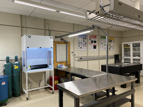
On Friday we completed assembly of the new stainless steel-topped benches in 1129. We then moved the clean and bake equipment from 1119 to its new larger space in 1129. This included the HEPA flow bench, ultrasonic washer, deionized water drum, nitrogen tanks, and forced-convection oven. The oven was re-anchored to the wall with earthquake restraints in its new location.

The power cords still need to be permanently routed, but the new clean and bake lab is otherwise ready for use.

Attachment 1: IMG_0781.png
IMG_0781.png
Attachment 2: IMG_0782.png
IMG_0782.png
  297   Wed Dec 20 10:33:34 2023 JonInfrastructureClean & BakeClean and bake lab migrated to 1129

Update: I have completed permanent routing of the electrical cables. I also ran the ultrasonic washer's drain line to the sink drain (the current hose does reach). The new clean and bake lab is now fully operational.

Quote:

[Jon, Tyler, Aiden, Luke]

On Friday we completed assembly of the new stainless steel-topped benches in 1129. We then moved the clean and bake equipment from 1119 to its new larger space in 1129. This included the HEPA flow bench, ultrasonic washer, deionized water drum, nitrogen tanks, and forced-convection oven. The oven was re-anchored to the wall with earthquake restraints in its new location.

The power cords still need to be permanently routed, but the new clean and bake lab is otherwise ready for use.


  303   Mon Jan 15 22:29:34 2024 JonInfrastructureGeneralCabinet installation & lab clean-up completed

[Jon, Tyler, Aiden, Shane, Pooyan, Michael, Cynthia, Luke]

On Wednesday, we completed long list of work towards making the new lab (1129) fully operational and enabling the next phase of FROSTI testing. 

Cabinet Installation

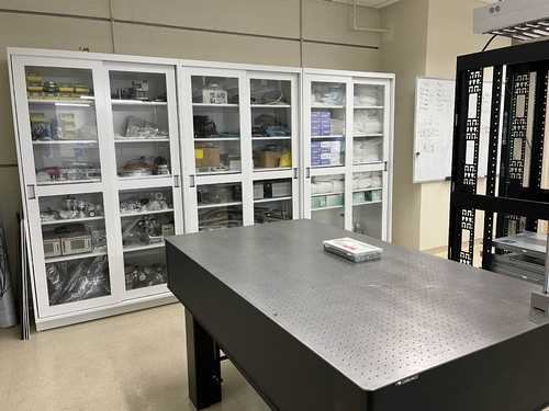
Three new VWR cabinets with sliding glass doors were installed in 1129. Each unit measures 48" (W) x 22" (D) x 84" (H) and sits along the back wall (see attachment 1). The 350-lb. cabinets were laid in place by Facilities on Monday and permanentized on Wednesday. Work included:

  • Earthquake anchoring to the masonry wall
  • Sliding glass doors leveled
  • Shelving installed
  • Wiping down of interior and exterior surfaces with IPA wipes

Server Rack Installation

A new Tripp Lite 42U open-frame rack was laid in place in 1129 and anchored to the floor (see attachment 1). This rack will house all of our general-purpose and simulation computers, which will be relocated from the 1119 rack at a later time.

Lab Clean-Up

Following installation of the new cabinets and rack, we proceeded to organize and clean both labs. Work included:

  • Moved parts and equipment into permanent storage in 1129 cabinets
  • Wiped down surfaces in 1119 and 1129 with polypropylene IPA wipes
  • HEPA-vacuumed floors of 1119 and 1129
  • Mopped floor in 1119 with Liquinox solution
  • Installed new sticky mats in 1119 and 1129
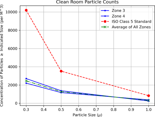
  • Regular cleanroom cleaning and particle counts (see 302)
  • Positioned new stainless steel gowning bench outside the cleanroom (see attachment 2)

At this point, the only piece of lab equipment still to be delivered is a HEPA garment cabinet for reusing our (semi-disposable) bunny suits. It is schedule to arrive in mid-February and will sit outside the cleanroom in 1119, in the former location of the HEPA flow bench.

Attachment 1: 1129.png
1129.png
Attachment 2: 1119.png
1119.png
  330   Tue Feb 20 08:01:30 2024 JonInfrastructureGeneralPower and network equipment installed in 1129 rack
[Jon, Tyler, Pooyan, Luis, Luke, Peter]

On Thursday we installed the power conditioning/distribution equipment and networking equipment in the new 1129 rack. The hardware is identical to the setup in the 1119 rack and includes:

  • Tripp Lite SU5KRT3UTF - 208V, 5kVA on-line UPS with 120V transformer
  • CyberPower PDU20M2F12R - metered power distribution unit, (14) NEMA 5-20R
  • Ubiquiti USW-Pro-48 - 48 port 10Gbps network switch

The UPS is connected to a 208V NEMA 6-30R outlet in the overhead cable tray, which is on the building's "standby" (backup power) circuit. An 8-ft L6-30 extension cord has been ordered to permanently run the power cable through the cable tray.

The network switch will be connected to a Cat6 cable that was recently run by ITS from the 1119 rack, allowing the lab's LAN to be extended into 1129. This Ethernet link remains to be tested.

Quote:

Server Rack Installation

A new Tripp Lite 42U open-frame rack was laid in place in 1129 and anchored to the floor (see attachment 1). This rack will house all of our general-purpose and simulation computers, which will be relocated from the 1119 rack at a later time.

Attachment 1: IMG_0924.jpeg
IMG_0924.jpeg
Attachment 2: IMG_0925.jpeg
IMG_0925.jpeg
Attachment 3: IMG_0921.jpeg
IMG_0921.jpeg
Attachment 4: IMG_0922.jpeg
IMG_0922.jpeg
  339   Sat Feb 24 08:53:38 2024 JonInfrastructureComputersMatlab upgraded to 2023b on Chimay
I upgraded Matlab on chimay to the latest stable release, 2023b. From some quick tests, it appears to be in working order. Let me know of any issues.
  377   Mon Jun 17 11:47:46 2024 LiuInfrastructureGeneralTemporary cooling units for the labs
Below are the temporary cooling units installed last week in labs 1119 and 1129. They are the temp. replacement for the building AC system, which will be shut down during the Physics roof replacement.
Attachment 1: 1119.jpg
1119.jpg
Attachment 2: 1129.jpg
1129.jpg
  379   Thu Jun 20 18:01:11 2024 JonInfrastructureComputersNew workstation ws3 in 1129
I have repurposed a spare Intel NUC to serve as the first of two planned workstations in 1129. Today I set it up with a fresh installation of Debian 12.5, assigned it the static IP address 192.168.1.15, and installed the LIGO CDS workstation packages. It is assigned the host name ws3. Temporarily, the mouse is borrowed from ws1 in 1119. We need to order another mouse as well as a 25-ft Ethernet cable for connecting the workstation to the 1129 switch, via the ceiling.
  382   Mon Jun 24 21:38:25 2024 PooyanInfrastructureComputersComputer server changes in 1119 and 1129

[Jon, Pooyan, Tyler]


A few computer machine changes have been made. 


  • Logrus moved from 1119 to 1129. It is up and running with the same IP address as before. 
  • A new Windows machine (host name: spica, IP:192.168.1.14) is installed in the 1119 server rack. It is connected to the RGA scanner with the serial port and is specifically used for that purpose. 
    • Update: The machine was off on 6/25, although it was left on 6/24. We think that it might have been because of Windows' default setting to suspend/hibernate the machine after idleness. To resolve this, I used  "powercfg /change" command to set all the following parameters equal to zero. The machine is still running on 6/26. 

    monitor-timeout-ac
    monitor-timeout-dc
    disk-timeout-ac
    disk-timeout-dc
    standby-timeout-ac
    standby-timeout-dc
    hibernate-timeout-ac
    hibernate-timeout-dc
  • A new Debian machine (hostname: megatron, IP:192.168.1.16) is installed in the 1129 server rack. This machine is intended to be used for FEA/simulation work. A new 2TB WD Green SSD is used as its main disk drive. 

     At the moment, “controls” is the only user, and there are no apps/libraries installed on the machine.

    • Update: Jon installed LIGO cds-workstation tools and MiniConda on 6/26. 
    • Update: Pooyan and Liu set the following conda environments:
      • Env named “finesse” with Python 3.12.3 and Finesse version 3.0a24 installed. Finesse was installed via the source code. The subdirectory “/home/controls/packages” is used to store the package sourcecodes.
      • Env named “fenicsx” with the same version of Python and Finesse as the previous env, with the latest version of FEniCSx (0.8) and the test-mass-thermal-state installed.  
Attachment 1: IMG_6889.jpg
IMG_6889.jpg
Attachment 2: IMG_6890.jpg
IMG_6890.jpg
  385   Wed Jun 26 15:33:41 2024 JonInfrastructureComputersNew workstation ws3 in 1129

Set-up of the first CDS workstation for 1129, ws3, is complete and the machine is ready for use. The login credentials are the same as the other lab machines.

All that now remains is to install a permanent cable tray for running the new Ethernet cables between the electronics rack and bench (they are currently dangling from the suspended lights).

Quote:
I have repurposed a spare Intel NUC to serve as the first of two planned workstations in 1129. Today I set it up with a fresh installation of Debian 12.5, assigned it the static IP address 192.168.1.15, and installed the LIGO CDS workstation packages. It is assigned the host name ws3. Temporarily, the mouse is borrowed from ws1 in 1119. We need to order another mouse as well as a 25-ft Ethernet cable for connecting the workstation to the 1129 switch, via the ceiling.

Attachment 1: IMG_1368.jpg
IMG_1368.jpg
  402   Thu Jul 11 21:01:37 2024 JonInfrastructureGeneralCable tray installed in 1129
Today I installed a 10' cable tray in 1129, for permanently routing Ethernet lines to the workstations. It is securely bolted to C-channels in the side wall and in the center cable tray.
Attachment 1: IMG_1395.png
IMG_1395.png
Attachment 2: IMG_1396.png
IMG_1396.png
  412   Fri Jul 26 17:25:42 2024 JonInfrastructureComputersNew workstation ws4 installed in 1129

Today I installed the second desktop workstation in 1129. The new machine is an Intel NUC13ANHi5, with a 12-Core Intel i5-1340P CPU, 32GB DDR4 RAM, and a 1TB SSD.

I loaded it with a fresh installation of Debian 12 and installed the LIGO CDS workstation (control room) tools. It is assigned the hostname ws4 and and the static IP address 192.168.1.19 on the local lab network. Like the other CDS workstations, there is just one user account accessible with the usual credentials.

The machine is fully set up and ready for use.

Attachment 1: ws4.jpg
ws4.jpg
  418   Tue Jul 30 07:42:47 2024 JonInfrastructureGeneralCable tray installed in 1119
Yesterday I installed another 5' cable tray in 1119, for permanently routing Ethernet lines to the L-bench. It is securely bolted to the top of the electronics rack, on one end, and to the top of the glass-door storage cabinet, on the other. This eliminates the need for the cable ramp which previously sat behind the rack.
Attachment 1: cable_tray_1119.jpg
cable_tray_1119.jpg
  437   Mon Sep 9 14:27:36 2024 PooyanInfrastructureComputersChimay backup attempt

One ongoing work is to make all lab machines automatically backed-up on Scribe on a daily basis. The updates should be boatable and stored for some time (potentially a few weeks) on Scribe. Making whole disk images has already been tried for some of the machines with no problems. (e.g., Cymac and WorkStations)

The same thing can not be done with Chimay though, as it currently has one huge RAID-controlled volume that stores all the information (OS, home directories, and NDS-downloaded data). Creating daily full disk images of such a system is not practical. 

Here is the plan we came up with to overcome this issue:

  1. Create one full disk image of Chimay and store it on Scribe (it was already done)
  2. Move the nds-downloaded raw data temporarily to Scribe and remove it from Chimay
  3. Make another full disk image of Chimay
  4. Burn this image to a single disk and boot chimay with it
  5. Restore the rest of Chimay disks and move the NDS data back


On the weekend (Sat and Sun 9/7-8) I tried to execute these steps. There wasn't enough free space left on Scribe to move all the NDS data to it, so I stored part of this data temporarily on WS4. Then I also checked storage-consuming directories and, in one case, removed some non-important stored files. As there was no free space left on Scribe to execute step no. 3, I initiated storing the image on WS3. Unfortunately, a couple of different trials of the image-creation process failed as there was not enough free space on WS3 to accommodate Chiamy image as well. I was not able to reduce the image size such that it can be stored on WS3. 


These are the options left for us to get this work done. 

  1. Distribute the NDS files between different machines to make enough free space on Scribe for the image and then follow the previous plan
  2. Shrink the Chimay drive size, create the image and then follow the previous plan
  3. Temporarily transfer some services to Megatrone (Network gateway, Wiki, elog) and recreate chimay and its services from scratch
  1   Sun Apr 10 15:39:49 2022 Rutuja GuravHowToComputer Scripts/ProgramsHowTo: Renew the Let's Encrypt SSL certificate using certbot

Port 80 is kept closed by default. This might be causing the certbot auto-renewal cronjob to fail. Therefore we must renew the certificate manually.


Step 1: Open port 80. (This is needed as the certificate renewal process runs some tests which requires client communication over port 80)


Step 2: Run the following command


sudo certbot certonly --force-renew -d richardsonlab.ucr.edu


Step 3: Confirm the certificate was renewed by running the following command


sudo certbot certificates

  2   Thu Jun 2 16:14:58 2022 JonHowToGeneralCustom conda environment on JupyterHub

Cross-linking instructions: How to run a Jupyter notebook in your custom Conda environment

  292   Fri Dec 15 14:03:02 2023 AidenHowToVACVacuum Chamber Opening
[Aiden]

1. Turn off the RGA filament and disconnect it.

2. Record the pressure and then close the angle valve and gate valve on the RGA line to isolate it from the system.

3. Turn off the backing and turbo pump and let the turbo pump spin to a stop by slowly leaking the chamber. The slower the safer.

4.Slowly open the vents on the chamber and the turbo pump. Making sure not to raise the pressure too fast.

5. Once done venting the chamber, open the lid by removing the bolts and prying the lid open with a long flat head screw driver.

6. Removed previous parts and placed them into clean bags. Place new parts inside of the chamber and group them together close to the center.

7. Place the lid back onto the chamber and tighten the bolts in a circular pattern until tightened all the way with the wrench.

8. Make sure all vents are closed and turn the backing pump back on.

9. The turbo pump can be turned back on when the pressure reaches e-1 torr.

10. Wait until the chamber reaches a pressure of e-6 torr before opening the angle and gate valve on the RGA line. After the RGA line is open and the pressure is still below e-6 torr, the RGA filament can be turned on and a leak test of the lid should be performed.

11. After the leak test shows no leaks, proceed with starting the low temp bake.

  14   Wed Dec 14 18:34:33 2022 JonConfigurationElectronicsAdapter for 532 nm laser power supply
I installed an EU-to-US plug adapter for the 532nm laser's 9V power supply. I then re-measured the laser's power with the correct supply voltage (previously we had been using a 6V supply). At 9V, the max power is 0.83 W, so the laser is confirmed to be Class 2 as labeled.
Attachment 1: laser_power.png
laser_power.png
  271   Mon Nov 20 10:10:50 2023 TylerConfigurationElectronicsRTD Logic/Schematic Diagrams

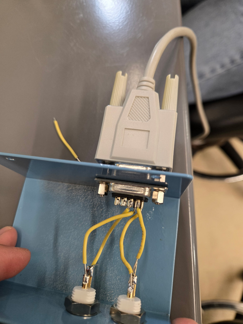
Below are a basic diagram of what the RTD measurement circuit logically looks like and an example schematic of the actual wiring. The schematic wiring will be placed internally into a chassis, connected to the RTDs via DB25 cable.

Note: The DB25 Breakout Board connector is Female, not Male.
Attachment 1: FIN_RTD_circuit.png
FIN_RTD_circuit.png
Attachment 2: Sample_Circuit_Schematic.png
Sample_Circuit_Schematic.png
  298   Fri Dec 29 16:02:27 2023 JonConfigurationElectronicsRTD Readout Chassis

The custom front and rear panels for the RTD readout chassis arrived last Friday. I installed them in the chassis frame to check their fit. They fit very well, so all that now remains is to complete the internal wiring and test the connections.

The chassis panel designs are archived to LIGO-D2300452 and LIGO-D2300453.

Quote:

Below are a basic diagram of what the RTD measurement circuit logically looks like and an example schematic of the actual wiring. The schematic wiring will be placed internally into a chassis, connected to the RTDs via DB25 cable.

Note: The DB25 Breakout Board connector is Female, not Male.
Attachment 1: front.jpeg
front.jpeg
Attachment 2: rear.jpeg
rear.jpeg
Attachment 3: overhead.jpeg
overhead.jpeg
  300   Tue Jan 9 12:08:59 2024 TylerConfigurationElectronicsRTD Readout Chassis Update

Below is the current state of the RTD readout chassis wiring. Initial continuity tests seem good, will run through one more time to confirm.

Quote:

The custom front and rear panels for the RTD readout chassis arrived last Friday. I installed them in the chassis frame to check their fit. They fit very well, so all that now remains is to complete the internal wiring and test the connections.

The chassis panel designs are archived to LIGO-D2300452 and LIGO-D2300453.

Quote:

Below are a basic diagram of what the RTD measurement circuit logically looks like and an example schematic of the actual wiring. The schematic wiring will be placed internally into a chassis, connected to the RTDs via DB25 cable.

Note: The DB25 Breakout Board connector is Female, not Male.


Attachment 1: IMG_8105.jpg
IMG_8105.jpg
  305   Tue Jan 16 12:20:21 2024 TylerConfigurationElectronicsRTD Readout Chassis Update 2

I performed another continuity test on the RTD chassis wiring, and everything seems to be set up correctly. The chassis should be ready for installation.

Quote:

Below is the current state of the RTD readout chassis wiring. Initial continuity tests seem good, will run through one more time to confirm.

Quote:

The custom front and rear panels for the RTD readout chassis arrived last Friday. I installed them in the chassis frame to check their fit. They fit very well, so all that now remains is to complete the internal wiring and test the connections.

The chassis panel designs are archived to LIGO-D2300452 and LIGO-D2300453.

Quote:

Below are a basic diagram of what the RTD measurement circuit logically looks like and an example schematic of the actual wiring. The schematic wiring will be placed internally into a chassis, connected to the RTDs via DB25 cable.

Note: The DB25 Breakout Board connector is Female, not Male.


Attachment 1: IMG_8146.jpg
IMG_8146.jpg
Attachment 2: IMG_8147.jpg
IMG_8147.jpg
  323   Tue Feb 13 11:54:45 2024 TylerConfigurationFLIRIn-Air Optical Test Configuration

Below is the proposed schematic for FROSTI optical testing, chosen so enough space is allotted for prototype assembly.

Steps to be taken include:

  1. Reconstruct FLIR staging apparatus
  2. Move test mass stand-in to cleanroom
  3. Mark FLIR camera position on cleanroom optical table at correct distance
  4. Run ethernet cable into cleanroom
  5. Move FLIR aside to allow for more assembly space
  6. Upon assembly completion, reposition FLIR onto optical table again

Tentative plan is to begin setup early next week.

Attachment 1: In-air_optical_test_sketch.png
In-air_optical_test_sketch.png
  451   Wed Oct 2 10:31:46 2024 Xuesi MaConfiguration Group Meeting Slides 10/2/2024

Group Meeting slides for Non-deterministic Heater Response.

Attachment 1: Group_Meeting_10_2.pdf
Group_Meeting_10_2.pdf
  517   Tue Feb 18 11:19:13 2025 Luke ConfigurationVACRepositioning of the lid's temperature probe
Before the recent bake I slightly repositioned the temperature probe on the lid from beside the heater tape to under the heater tape. This was done to better know and control the temperatures of the chamber while baking. It has appeared to work with the temperatures being held very close to the 120C target.
ELOG V3.1.3-7933898