| ID |
Date |
Author |
Type |
Category |
Subject |
|
83
|
Fri Apr 28 11:21:01 2023 |
Peter | Update | VLC Update | Laser intensity/polarization drift measurements |
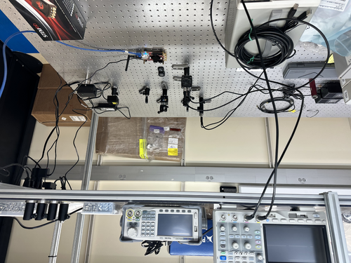
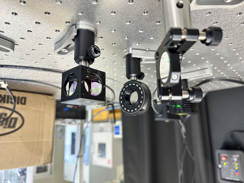
| The Digi-key cables have arrived, and I have began implementing them in the intensity drift measurements.
There was a slight problem initially in connecting the SMA to BNC cables from the photodiode to the red pitaya, since the red pitaya was way on the other side of the lab. Cao and I connected the red pitaya to a new ethernet cable that extended far enough for the red pitaya to sit comfortably on the breadboard with the optics.
Right now the PDAs are not connected to the red pitaya. I have connected them to the oscilloscope in order to read out how much voltage they produce upon incidence of 532nm laser light. This was done in order to make sure that they do not surpass the limit of the red pitaya (+-1V). I have not acquired a value for the readout voltage of the PDAs since I had to go to class. I will gather this preliminary data soon. |
| Attachment 1: IMG-0183.jpg
|
|
|
88
|
Mon May 1 18:56:57 2023 |
Peter | Update | VLC Electronics | 532nm Intensity Measurement |
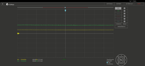
| I've configured the two PDA's to the Red Pitaya. I put a 50 ohm resistor connector to each red pitaya input port. This was because the oscilloscope showed that the voltage reading from the P polarization PDA was almost at 1V, which was the limit of the red pitaya. Once both S and P polarization PDA's were connected, I opened the red pitaya's oscilloscope. A screenshot of the voltage readings is shared below. Channel 1 (Yellow) is for S polarization. Channel 2 (Green) is for P polarization. It would seem that there is a significant amount of polarization in the P direction as opposed to the S direction.
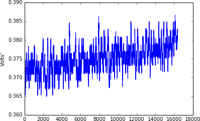
I then tried running the template time series measurement within the python notebook from channel 1 only. The python notebook graph is shown below. I have not figured out what are the units of time on the x axis, and I have not figured out how to change the amount of time that the red pitaya takes data. A plot of the time series measurement is shown below. |
| Attachment 1: graphs.jpg
|
|
| Attachment 2: Time_Series_Trial_1.png
|
|
|
89
|
Tue May 2 15:55:33 2023 |
Peter | Update | VLC Electronics | 532nm Intensity Measurement |
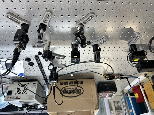
| I changed the 1/2 wave plate from the lens mount to the rotational optic mount. This allowed me to rotate the 1/2 wave plate, which changed the respective polarization power transmitting through S and P polarization. Initially, more power was coupled into the P polarization. Now, with the 1/2 plate rotated, both channels are experiencing the same voltage reading. Before feeding the PDA signals into the red pitaya, a 50 ohm terminator had to be placed at the SMA connection port so that the input power into the red pitaya did not exceed 1V. With this configuration, both channels experience about 0.35mV. (See attached)
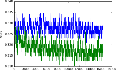
I then opened the Jupyter notebook, and ran a demo time series measurement from the red pitaya. This time, I was able to get a plot featuring both channels (green is P polarization. Blue is S polarization). The plots are consistent with what is shown in the red pitaya oscilloscope. However, the time collection (I'm assuming) only runs for about 0.018s. I will have to write some of my own code to loop over this measurement, and collect more data. |
| Attachment 1: IMG-0221.jpg
|
|
| Attachment 2: IMG-0222.jpg
|
|
| Attachment 3: graphs(1).jpg
|
.jpg.png)
|
| Attachment 4: Time_Series_Trial_2.png
|
|
|
92
|
Thu May 4 14:01:10 2023 |
Peter | Update | VLC Electronics | 532nm Intensity Measurement |
| I adjusted the rotational mount of the wave plate to see if the power can be 100% coupled into either S or P polarization. The images shown below of the oscilloscope indicate that this is not possible. The minimum transmitted power we can obtain in either S or P polarization is 75mV. The maximum voltage we obtain in either S or P polarization is ~ 740mV. This means that at a maximum, we can obtain ~ 90% polarization in either direction, indicating that our laser has a slightly elliptical polarization. |
| Attachment 1: graphs(3).jpg
|
.jpg.png)
|
| Attachment 2: graphs(2).jpg
|
.jpg.png)
|
|
93
|
Mon May 8 12:00:03 2023 |
Pamella, Shane, Julian | Update | General | Cleanroom particle counts and cleaning the cleanroom. |
[Pamella,Julian, Shane]
Today we cleaned the clean-room (floor, surfaces) and particle count.
10:00 am: Started particle count.
- Zone 3:
- 0.3u: 1330
- 0.5u: 540
- 1.0u: 415
- Zone 4:
- 0.3u: 290
- 0.5u: 83
- 1.0u: 0
Clean-room:
- 10:30 am: Started wiping down the surfaces inside the clean-room
- 10:41 am: Finished wiping down the surfaces inside the clean-room and Started vacuuming the clean-room.
- 10:58 am: Finished vacuuming the clean-room.
- 11:00 am: Started mopping on the floor.
- 11:20 am: Finished mopping on the floor and started wiping on the floor.
- 11:34 am: Finished wiping on the floor.
- 11:35 am: Started the particle count.
- 11:57 am: Finished the particle count.
- Zone 3
- 0.3u: 997
- 0.5u: 290
- 1.0u: 207
- Zone 4
- 0.3u: 374
- 0.5u: 207
- 1.0u: 207
|
|
96
|
Wed May 10 10:49:34 2023 |
Aiden | Update | General | RGA Software |
| [Aiden, Cao]
Went over how to use the RGA software, how to change the graph units, scaling and mass detection. Also went over how to remove the RGA from the vacuum system as well as procedure for turning it on. |
|
99
|
Tue May 16 11:56:33 2023 |
Peter | Update | VLC Electronics | 532nm Intensity Measurement |
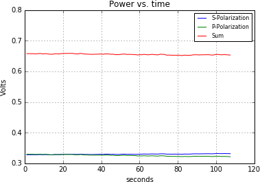
| With the configuration the exact same as before, I used the Jupyter notebook in the red pitaya's development package to collect data from both input channels. Last week, I was able to take data, yet only for a very short period of time, and I did not know how to change it. I went online to the red pitaya's user manual to figure out how to change the sampling period for longer. The link to the page is here: https://redpitaya.readthedocs.io/en/latest/appsFeatures/examples/acqRF-samp-and-dec.html#s-rate-and-dec Though I now know how to change the period of time for which data is taken, the maximum amount of time is still only about 8 seconds. So with help from Cao, we looped over the data taking samples, and got a mean value for each iteration. We then put all those mean values in an array, and plotted it. Below, we see a plot of both the S and P polarizations, and a sum of both of them. As seen in the graph, I have set the time to be able to take data for almost 2 minutes. There is some slight drift in the respective intensities. The next steps I believe are to convert the units into watts, and take data for longer periods of time. |
| Attachment 1: Time_Series_Trial_3.png
|
|
|
100
|
Wed May 17 12:18:08 2023 |
Pamella, Julian and Shane | Update | General | Cleaning room and particle count |
[Pamella, Julian and Shane]
Particle count:
- 10 am: Started particle count
- Zone 3 :
- 0.3u: 1288
- 0.5u: 332
- 1.0u: 124
- Zone 4 :
- 0.3u: 498
- 0.5u: 166
- 1.0u: 83
- 10:40 am: Checked the surfaces inside the cleanroom.
- 10:50 am: Started vacuuming the cleanroom.
- 11:15 am: Started mopping the cleanroom.
- 11:35 am: Started wiping the cleanroom floor.
- 11:40 am: Finished cleaning the cleanroom.
- 11:41 am: Started the particle count.
- 12:17 am: Finished the particle count.
- Zone 3 :
- 0.3u: 3782
- 0.5u: 706
- 1.0u: 207
- Zone 4 :
- 0.3u: 374
- 0.5u: 83
- 1.0u: 83
|
|
101
|
Thu May 18 14:07:08 2023 |
Peter | Update | VLC Update | 532nm Intensity Measurement |
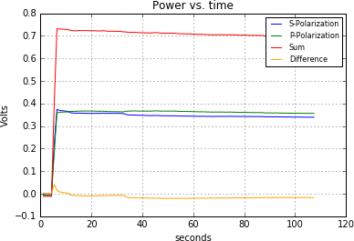
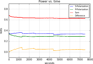
| I figured out a method in which to capture power measurements including the initial seconds in which the beam is first turned on. I first clear and restart the kernel of the python notebook. Then I run the command to connect the red pitaya oscilloscope package to the input data being taken in both channels. To my understanding, this allows for data acquisition as the code compiles. I then started looping the 1.074s trigger bunches, and then roughly 2 seconds after I ran that command, I went and turned on the laser. The first plot shown is a 2 minute practice trial of me trying this technique to make sure that the python package was correctly registering the input of the red pitaya. It is clear that initially the laser is off, and then as I turned it on, the voltage in each channel spikes, which is compelling evidence that the code is working. I then set the data collection to be 7518 seconds (7000 loops), which is about 2 hours and 5 minutes. I repeated the same technique as for the first plot, only changing the amount of time I collected data. The second plot shown here is the voltage being read in each channel as a function of time. As we can see, over a period of hours, the intensity drifts quite dramatically for the first several minutes, and then begins to stabilize slightly. However, there are still some strong sudden fluctuations in each channel. |
| Attachment 1: Time_Series_Trial_4.png
|
|
| Attachment 2: Time_Series_Trial_5_2hrs.png
|
|
|
102
|
Mon May 22 16:43:28 2023 |
Peter | Update | VLC Electronics | Laser intensity/polarization drift measurements |
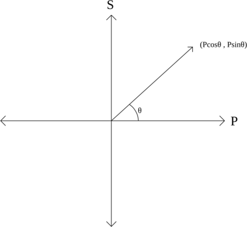
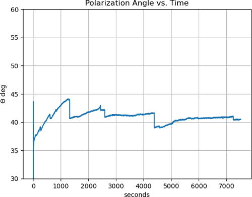
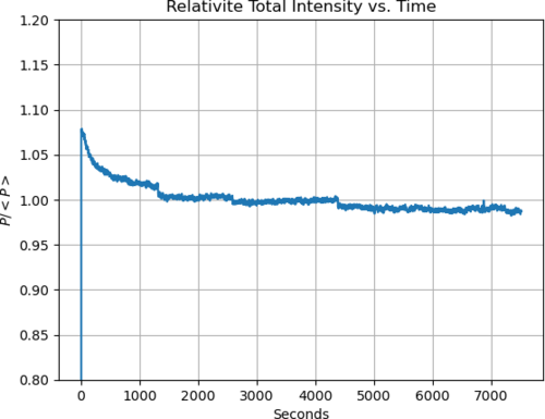
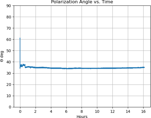
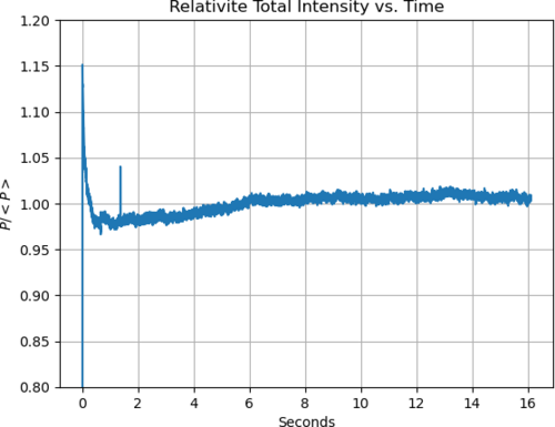
| In order to fully analyze the polarization data taken last Thursday, I needed to convert the signal output (which is in volts) to power (units of watts). I used the power meter to accomplish this. Keeping the exact same configuration of PD's and beam splitting, opened the red pitaya's oscilloscope package. I then took the power meter, and held it in front of the PD to measure the amount of Watts at each PD. I then wrote down the corresponding voltage being seen in the red pitaya. I took 5 sets of measurements for each PD to get experimental accuracy. I then used a simple y = mx + b fit to find out the constant m that converts the input wattage into voltage. For the s polarization, the conversion factor is 0.83. For the p polarization, the conversion factor is 1.12. I then used this data to plot polarization angle as a function of time, and the relative intensity drift as a function of time. The plots are shown below. The physical meaning of the polarization angle is shown in the unit circle diagram below, in which P is the total power. |
| Attachment 1: S-P_Polarization_Diagram.svg
|
|
| Attachment 2: Polar_angle_vs_time.png
|
|
| Attachment 3: Rel_Intens_vs_time.png
|
|
|
104
|
Mon May 22 17:08:50 2023 |
Pamella | Update | FLIR | FLIR project - Installing the mask. |
[Pamella]
- The new mask for the reflector.
- 1:40 pm: Started reconfiguration on the FLIR camera project. Changed the old bridge for the new mask-bridge.
- 2:00 pm: Started figure out the best way to cutting the aluminum foil with the new mask. Unfortunately, I had been some problems for cutting the perfect shape triangles with the mask because the size inside the triangle is different (smaller) than cutter/knife, so is not able to do the cut with precious and carefully then maybe I need other tool for this job. Also I tried use the scissor, didn't work. However, just for the initial testing I worked with the not perfect triangles shape.
- 2:49 pm: Started installing/attaching the light in the mask.
- 3:21 pm: Finished installing the light in the mask-bridge.
- 3:22 pm: Started testing the current and voltage in the new mask-bridge for make sure the light cable is working well.
- 3:25 pm: Started measurement the resistance with multimeter.
- 3:29 pm: The measurement looks fine. The multimeter show us 14.1 Ω;
- 3:38 pm: Started putting the reflector( with the mask attached) in front of the black wall.
- 3:44 pm: Started roll the testing with the python code to observer the behavior with this new mask. Parameters: 0.14 A and 1.9 V.
- 4:00 pm: Started snapping. Parameters: 0.13 A and 1.9 V. Final Temperature: 42.7 C.
- 4:02 pm: Started trying again with more current. Parameters: 0.16 A and 2.2 V.
- 4:36 pm: Started snapping. Parameters: 0.16 A and 2.2 V. Final Temperature: 50.3 C.
- 4:55 pm: For now, we can't see the triangles in the snap so i need do some changes.
- To do:
- Change the FLIR camera position for the other side on the table.
- Start the test without the black wall.
- Try a better tool to cut the triangles inside the 3D-mask.
|
| Attachment 1: Mask.jpg
|
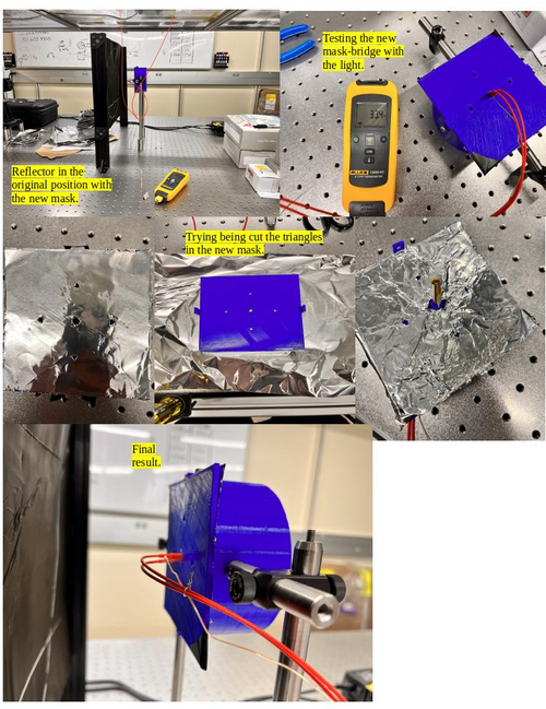
|
| Attachment 2: AcquisitionImage(May-22-2023_16_35).jpg
|
.jpg.png)
|
| Attachment 3: AcquisitionImage(May-22-2023_16_01).jpg
|
.jpg.png)
|
|
105
|
Tue May 23 16:52:56 2023 |
Pamella | Update | FLIR | FLIR project - Reinstalling the mask and Reconfiguration FLIR position. |
[Pamella]
Reinstalling the mask and Reconfiguration FLIR position.
- Today i change the aluminum foil inside the 3D mask. After some tries i was able to have a better shape for the triangles.
- I reinstalled the connections (the light with the thermometer point). Also i checked for the focal point inside the reflector, looks fine.
- I did a reconfiguration for the initial tests, without the black wall. I moved the FLIR camera and the Reflector-Mask for other position on the table.
To do:
- Start the test with the power current on.
- I need figure out a better position for the light cables because in front of the mask isn't a good position for us do measurement.
|
| Attachment 1: AcquisitionImage(May-23-2023_16_36).jpg
|
.jpg.png)
|
| Attachment 2: Reconfiguration.jpg
|
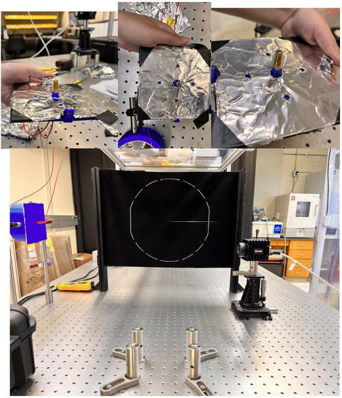
|
|
106
|
Wed May 24 14:06:27 2023 |
Pamella | Update | FLIR | FLIR project - Tests |
[Pamella]
Initial tests
- 10:30 am : Started trying take some test with the new position/configuration between the 3D reflector-mask and the FLIR camera.
- 10:41 am : Started running the python code and take a snap. Parameters: 0.10 A, 1.4 V.
- 10:50 am : Started take the snap.It is possible see the triangles, this is a good thing. Negative thing: The middle/center point for the light maybe would be some problems for the future measurements. Parameters: 0.10A, 1.4 V and 41 C.
- 11:00 am : Started working to better align the entire structure. And double-check the distance between the 3D reflector-mask and the FLIR camera, following the instructions in Cassidy's Final FLIR Project Report.
- 11:10 am : Difficult point: I tried to attach the complete FLIR camera to the table, but I had a problem to secure the four screws to the table, the distance is not completely compatible with the table stand. Yesterday I just put two screws in the diagonal position, it works fine, but it's not the correct position to work.
- 12:00 am : Note: Two triangles take more long time to come back a not (low) irradiation position (east and south point).
- 2:00 pm : Started running the python code again.
- Parameters: 0.13 A 1.8 V.
- 2:30 pm: Started take snap. Parameters: 0.13 A, 1.8 V and 49.1 C
- 3:00 pm: Note: This time every triangles was able to come back a low irradiation position.
|
| Attachment 1: AcquisitionImage(May-24-2023_10_50).jpg
|
.jpg.png)
|
| Attachment 2: thumbnail_IMG-7146.jpg
|
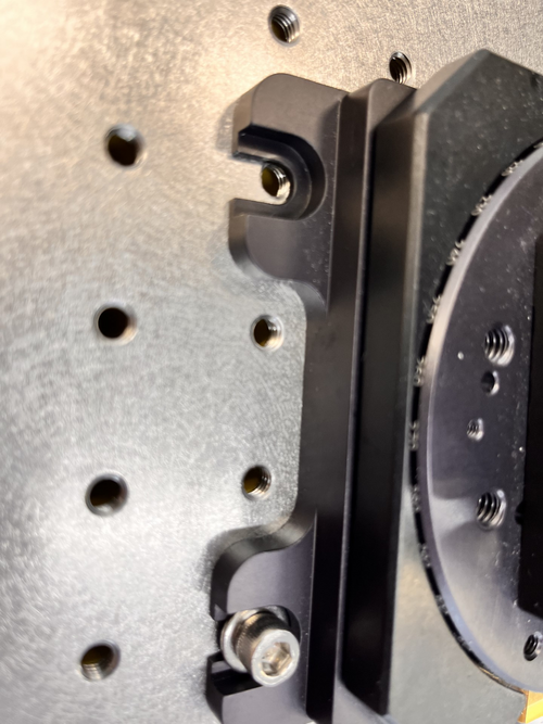
|
| Attachment 3: AcquisitionImage(May-24-2023_14_30).jpg
|
.jpg.png)
|
|
107
|
Wed May 24 14:28:26 2023 |
Peter | Update | VLC Electronics | Laser intensity/polarization drift measurements |
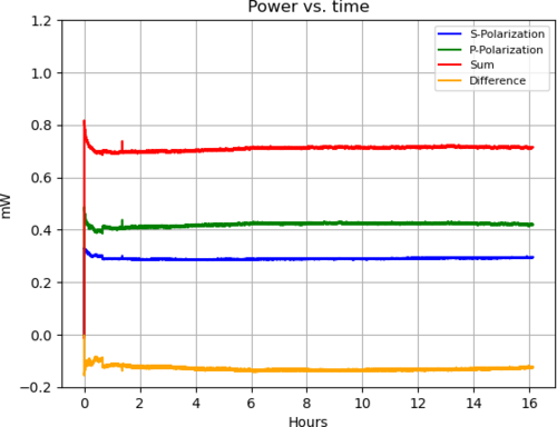
| I went in and took polarization drift data for 16 hours. The run started at 6:08pm and finished at 9:15am the next day. The four plots below are the same plots shown for the 2 hour collection and previous trials, except they extend to 16 hours. The only one that is different is the Power vs. Time graph. This is a graph of the actual incoming power of the laser (as opposed to the signal voltage that the PDA's output into the red pitaya). This was done using the calibration factors of the respective PDA's and as we can see, since there is a difference in the calibration factors between detectors, there is a difference in the power that's coupled into S and P polarization. |
| Attachment 1: Time_Series_Trial_7_16hrs.png
|
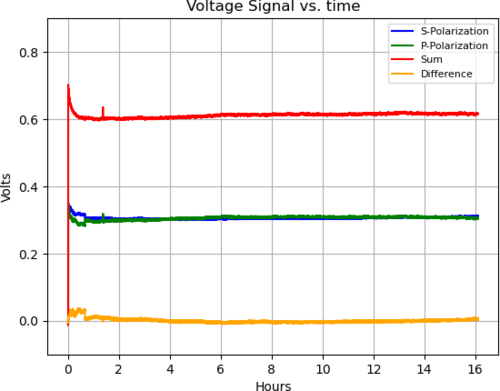
|
| Attachment 2: Power_vs_Time_16hrs.png
|
|
| Attachment 3: Polar_angle_vs_time_16hrs.png
|
|
| Attachment 4: Rel_Intens_vs_time_16hrs.png
|
|
|
108
|
Tue May 30 14:51:27 2023 |
Pamella | Update | FLIR | New 3D mask - Bigger triangles shapes. |
[Pamella]
Change the 3D mask
- Started removing the old mask in the reflector.
- Started cutting the new aluminum lid for the new 3D mask and assembling in the 3D mask.
- Started doing the new cable connections for the light.
- Started testing the resistance in the new cable connections. The multimeter show us 14.2 Ω.
- Started attaching the mask with the light and the thermometer sensor.
- Started assembling the 3D mask in the reflector.
- Started the initial tests.
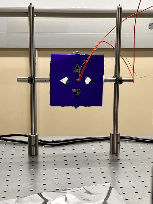
- 2:00 pm: Started testing the new mask. Parameters: 1.4 V 0.1A and 27 C
- 2:38 pm: Started taking snap. Final parameters:1.4 V 0.1A and Temperature: 39.9 C
- Started doing some adjustments in the triangles shapes for the futures tests.
|
| Attachment 1: AcquisitionImage(May-30-2023_14_38).jpg
|
.jpg.png)
|
| Attachment 2: thumbnail_IMG-7303.jpg
|
|
|
109
|
Wed May 31 11:42:16 2023 |
Pamella, Julian and Shane | Update | General | Cleaning room and particle count |
[Pamella, Shane and Julian]
Cleaning room and particle count
- 09:58 am: Started the particle count
- Zone 3:
- 0.3u : 1,995
- 0.5u : 540
- 1.0u : 0
- Zone 4:
- 0.3u : 124
- 0.5u : 0
- 1.0u : 0
- 10:25 am: Started checking the surfaces inside the cleanroom.
- 10:30 am: Started vacuuming the floor.
- 10:45 am: Finished vacuuming the floor.
- 10:46 am: Started mopping the floor.
- 10:58 am: Finished mopping the floor.
- 11:00 am: Started wiping floor with polypropylene wipes.
- 11:03 am: Started and finished cleaning the mop buckets.
- 11:15 am: Finished wiping floor with polypropylene wipes.
- 11:16 am: Changed sticky floor mats.
- 11:20 am: Started the particle count.
- Zone 3:
- 0.3u : 2,951
- 0.5u : 872
- 1.0u : 207
- Zone 4:
- 0.3u : 374
- 0.5u : 83
- 1.0u : 0
|
|
110
|
Wed May 31 12:16:28 2023 |
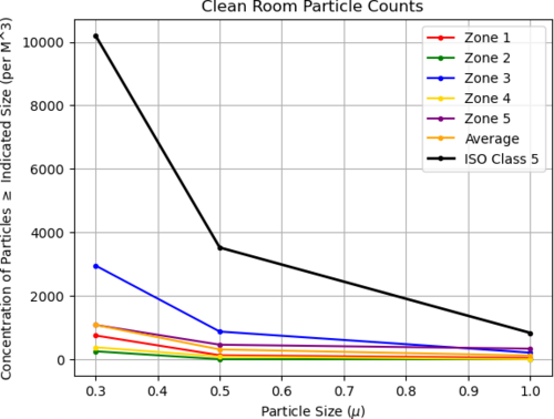
Shane | Update | Cleanroom | cleanroom particle counts (full 5 zone measurement) |
| Attached is the full 5 zone particle measurement for the cleanroom after this week's cleaning, 5/31/23. |
| Attachment 1: 23.png
|
|
|
112
|
Wed May 31 16:55:55 2023 |
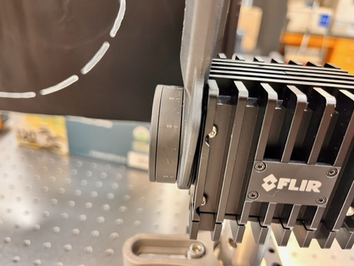
Pamella | Update | FLIR | FLIR- Focus distance |
[Pamella and Tyler]
- We changed the FLIR Focus Distance for around 0.55 m.
- Note: The old focus distance was 1.3 m.
- We tested this new focus distances and looks good. I attached a snap below.
Parameters: 0.1 A , 1.5 V and 38.4 C.
|
| Attachment 1: AcquisitionImage(May-31-2023_16_40).jpg
|
.jpg.png)
|
| Attachment 2: thumbnail_IMG_7310.jpg
|
|
|
113
|
Thu Jun 1 14:41:36 2023 |
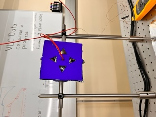
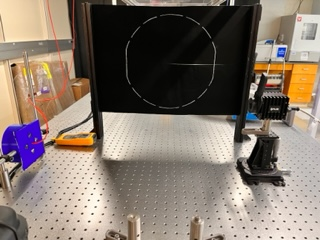
Pamella | Update | FLIR | FLIR project - Test without the black wall. |
[Pamella]
Test without the black wall.
General test:.
- 11:15 am : Started running the code. Parameters: 0.11 A, 1.9V and focus distance around 0.55m.
- 11:28 am : Started snapping the screen. Parameters: 0.12 A, 1.8V and 44.1 C .
First trying:
- 01:18 pm : Started testing and collection data. Parameters: 0.09 A, 1.4V. Reference position: (0,0).
- 01:28 pm : Started snapping the screen. Parameters: 0.10 A, 1.5V and 37.9 C. Reference position: (0,0).
Second trying:
- 01:34 pm : Started testing and collection data. Parameters: 0.08 A, 1.4V. Reference position: (0,-0.10).
- 01:44 pm : Started snapping the screen. Parameters: 0.09 A, 1.7V and 35.8 C. Reference position: (0,-0.10).
Third trying:
- 01:50 pm : Started testing and collection data. Parameters: 0.08 A, 1.3V. Reference position: (0,-0.05).
- 02:00 pm : Started snapping the screen. Parameters: 0.09 A, 1.4V and 35.4 C. Reference position: (0,-0.05).
Fourth trying:
- 02:04 pm : Started testing and collection data. Parameters: 0.09 A, 1.3V. Reference position: (0,0.05).
- 02:14 pm : Started snapping the screen. Parameters: 0.11 A, 1.6V and 41.7 C. Reference position: (0,0.05).
Note: So today i tried collecting data for every possible position in Y (height) way for starting analyses and compares the triangles shapes. I realize maybe we get a problem because i keep the same time in every try but the final temperature and the parameters change every time, so i will try do a better system to keep the parameters equal, maybe i can wait the reflector be back to a normal temperature after every test or keep the system on all the time and just change the reflector position. I pretty sure this was the problem.
|
| Attachment 1: thumbnail_IMG_7316.jpg
|
|
| Attachment 2: AcquisitionImage(Jun-01-2023_14_14).jpg
|
.jpg.png)
|
| Attachment 3: thumbnail_IMG_7320.jpg
|
|
|
114
|
Fri Jun 2 14:28:40 2023 |
Pamella | Update | FLIR | FLIR project - Test without the black wall. |
[Pamella]
Test without the black wall.
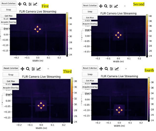
Note: So today i collected data for some positions in axis Y (height) for starting analyses and compares the triangles shapes. I tried keep the same parameters every time.
First position:
- 01:20 pm : Started testing and collection data. Parameters: 0.10 A, 1.6V. Reference position: (0,0.05).
- 01:30 pm : Started snapping the screen. Parameters: 0.10 A, 1.6V and 37.7 C. Reference position: (0,0.05).
Second position:
- 01:34 pm : Started testing and collection data. Parameters: 0.10 A, 1.6V Reference position: (0,0).
- 01:44 pm : Started snapping the screen. Parameters: 0.10 A, 1.6V and 40.6 C. Reference position: (0,0).
Third position:
- 01:50 pm : Started testing and collection data. Parameters: 0.10 A, 1.6V. Reference position: (0,-0.05).
- 02:00 pm : Started snapping the screen. Parameters: 0.10 A, 1.6V and 39.1C. Reference position: (0,-0.05).
Fourth position:
- 02:03 pm : Started testing and collection data. Parameters: 0.10 A, 1.6V. Reference position: (0,-0.10).
- 02:13 pm : Started snapping the screen. Parameters: 0.10 A, 1.6V and 39.6 C. Reference position: (0,-0.10).
|
| Attachment 1: 1Axis_y___tests.jpg
|
|
|
115
|
Tue Jun 6 16:04:46 2023 |
Aiden | Update | General | Water |
| Aiden went and refilled the de-ionized water to continue clean and bake batches. |
|
116
|
Tue Jun 6 16:15:09 2023 |
Peter | Update | VLC Update | Launch Optics for Visible Light Cavity |
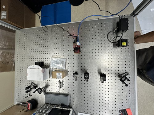
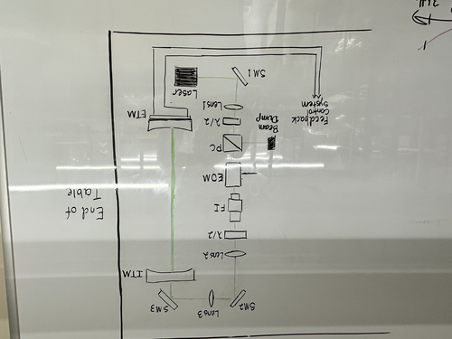
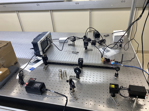
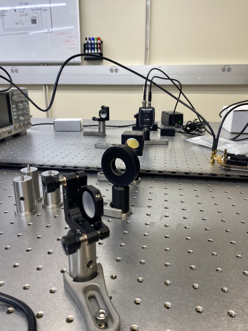
| I assembled the first few components of the launch optics for the visible light cavity. Below is an image of the current table configuration, and the image is how the cavity will be oriented on the table. |
| Attachment 1: IMG-0882.jpg
|
|
| Attachment 2: IMG-0883.jpg
|
|
|
117
|
Thu Jun 8 14:51:58 2023 |
Pamella | Update | FLIR | FLIR- Distance |
[Pamella, Tyler]
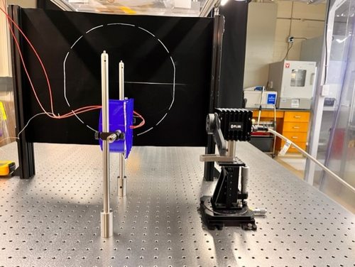
- Today we change the distance between the FLIR camera and reflector (3D-Mask with mirrors and light). Now the distance is 0.2032 m.
- Note: This distance is just for take a snap most close possible but we need move again for a little far way because in this distance we can't move up and down the reflector for have data to compare.
|
| Attachment 1: AcquisitionImage(Jun-08-2023_14_33).jpg
|
.jpg.png)
|
| Attachment 2: thumbnail_IMG_7441.jpg
|
|
|
118
|
Mon Jun 12 12:15:10 2023 |
Pamella | Update | FLIR | FLIR- Take data in the closest point. |
[Pamella]
- Used the closest point possible for the reflector in front of the FLIR camera.
- 11:32 am : Turned on the electronic device (current on) for started taking data.
- 11:50 am: Started checking the temperature and the parameters.
- 12:04 pm: Started taking snap after waited for 30 minutes with the current on. Parameters: Current: 0.13A , Volt: 1.8V and Temperature: 51.4 C.
- Note: This snap is in the most close point possible, after that I should be change the reflector position and also the optical focus distance in the FLIR camera.
We can see, in the photo attached below, thought in this closest position the cable connect to reflector is a bit problem to take a good snap also the have issues to keep very uniform triangles (temperature) in the reflector.
- To do: I'll change the position on the light inside to see if the problem it is in the focal point inside the reflector (mirror).
|
| Attachment 1: AcquisitionImage(Jun-12-2023_12_04).jpg
|
.jpg.png)
|
|
119
|
Mon Jun 12 18:52:00 2023 |
Pamella | Update | General | Heater system parts - Wiped and bagged |
[Pamella]
Cleaning the heater system parts.
- 04:32 pm: Started wiping the heater system parts.
- 06:38 pm: Finished wiping the heater and some parts to the system. I wiped, tagged and bagged the heater system, power cables, adapter cables and power connectors. Also I wiped, bagged and tagged the aluminum foil tape.
- 06:43 pm: I putted all bags inside the cleanroom.
- To do: I started but I was not able to finished wiping the heating and cords for the heater system so I will finished this parts after.
- I attached the photos below.
|
| Attachment 1: heater_equipment_wiped.jpg
|
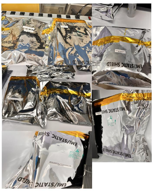
|
|
120
|
Tue Jun 13 10:28:50 2023 |
Pamella | Update | General | Wiped and bagged the heating and cords. |
[Pamella]
- Cleaning the heater system parts.
- 09:13 am: Started wiping the last parts for the heater system (heating and cords).
- 10:18 am: Finished wiping the parts to the heater system (heating and cords). I wiped, tagged and bagged the heating and cords.
- Note: In some parts looks like the silicone insulation material is having some sort of residue on the wipe so I wiped very careful this part and just for a few minutes.
- 10:23 am: I putted all bags inside the cleanroom.
I attached the photos below. |
| Attachment 1: heater_cords_wiped.jpg
|
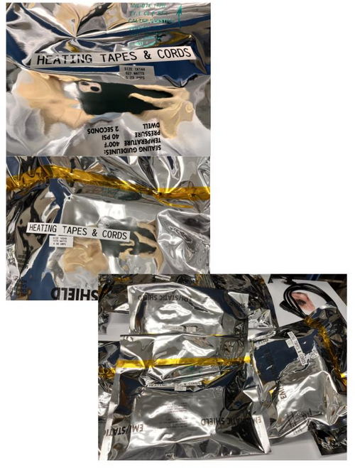
|
|
123
|
Tue Jun 13 21:33:46 2023 |
Pamella | Update | General | New cabinet for PPI |
[Pamella and Dr.Richardson]
Dr. Richardson installed the new cabinet outside the room for the PPI equipments, and then I wiped all surfaces inside and outside of the new cabinet.
Dr.Richardson and I have finished organizing the PPI within the new cabinet. Also we have new supplies of gloves, and will likely have more supplies for other PPIs soon. |
|
124
|
Wed Jun 14 15:35:36 2023 |
Pamella | Update | VAC | Heating system installation |
[Pamella and Cao]
Heating system installation - Second day.
- Today we kept installing the equipment for the heating system.
- First: Started installing the two heating cable around the chamber vacuum, the arms and covered it with aluminum tape.
- Second: Started installing the insulation stuff around the vacuum chamber and around the connections points (the arms) in the vacuum chamber.
- Third:Started installing the heater system (electronic device) and tried testing.
-
Note: The around part of the chamber vacuum was difficult to cover, so we spent a little time on. Also one heater system electronic device wasn't working because one fuse is burned so we could not finished this part and we need wait for a new one to replace and working on it.
|
| Attachment 1: heater_equipment_install.jpg
|
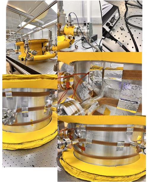
|
|
125
|
Fri Jun 16 16:17:13 2023 |
Pamella | Update | FLIR | FLIR - Change the position |
[Pamella]
Today I change the distance between the FLIR camera and reflector (3D-Mask with mirrors and light). Now the distance is 0.3282 m.
- Note: In this distance is possible move up and down the reflector and take data to compare.
- The focal point inside the reflector keeping like little problem, every time I tried adjust this I got some triangles is not with "perfect emission" (looks like different than the others). Also if I move up or down the focal point inside the reflector have some issues as well.Therefore I am working on that.
|
| Attachment 1: IMG-7637.jpg
|
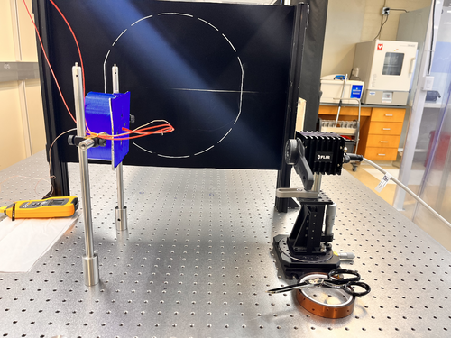
|
|
126
|
Fri Jun 16 17:40:28 2023 |
Aiden | Update | Clean & Bake | Clean and Bake Batch 14 |
| Cleaned and Baked the new and 2.75" copper gaskets for the vacuum system. Cleaned them with liquinox in the ultra sonic washer for 10 minutes. Then dried them with nitrogen. Then put the copper parts into the oven for the following steps; 1. Ramp to 100 degC in 15 minutes 2. Dwell at 100 degC for 30 minutes 3. Ramp to 175 degC in 30 minutes 4. Dwell at 175 degC for 24 hours 5. Turn off
Also bagged and tagged the parts from Batch 13 and placed them into the clean room on the computer table. |
| Attachment 1: IMG_4441.jpg
|
|
| Attachment 2: IMG_4440.jpg
|
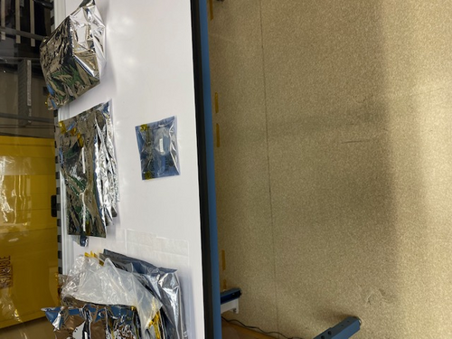
|
|
127
|
Mon Jun 19 11:20:57 2023 |
Pamella | Update | FLIR | FLIR - Fixed some problems |
[Pamella]
- 08:59 am: Turned on the electronic device (current on) for started taking data.
- 09:37 am: Tried understanding the error in the focal point. I realized the pillars was in the wrong place and because of that we got problems to keep the reflector in the correct position to FLIR focus.
- 09:58 am: Started checking the temperature and the parameters.Changed the pillars to the original position (0.5645m) just for checking with the problem was the pillar in the wrong place.
- 10:06 am: Changed the reflector to point (0.3282m) and now in the correct position for the pillars. Started take snap and collecting data. I moved up and down the reflector for got data to compare later.
- 10:37 am: Used the closest point possible for the reflector in front of the FLIR camera with the correct spot for the pillars.(0.2032m)
- 11:00 am: Started taking snap after kept the current on for a few hours. Parameters: Current: 0.10A , Volt: 1.3V and Temperature: 41.9 C.
- I attached below the snap in the most close point possible, now i can see a better photo and I think a fixed the problem about the focal point in the reflector for have more uniformity between the triangles, isn't perfect yet but now is just some adjustments. Furthermore after that I should be change the reflector position and also the optical focus distance in the FLIR camera and try use the black wall.
|
| Attachment 1: AcquisitionImage(Jun-19-2023_11_00).jpg
|
.jpg.png)
|
|
128
|
Tue Jun 20 17:28:23 2023 |
Pamella | Update | Electronics | Heater system parts - Wiped |
[Pamella]
Wiping the heater system parts.
- 04:37 pm: Started wiping the electronic device part for the heater system (HL101 Series Digital Benchtop temperature limit control).
- 05:19 pm: Finished wiping the parts to the heater system (HL101 Series Digital Benchtop temperature limit control). I wiped the HL101 Series Digital Benchtop temperature limit control and I didn't bagged and tagged because we should install that soon.
- 05:23 pm: I putted heater electronic device inside the cleanroom without the bag. Also the electronic device is near to the vacuum chamber and the other parts to heater system.
- I attached the photo below.
|
| Attachment 1: IMG_7696.jpg
|
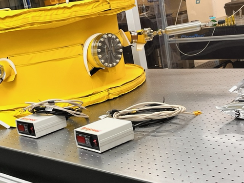
|
|
131
|
Thu Jun 22 13:58:00 2023 |
Pamella, Julian and Shane | Update | Cleanroom | Cleaning and Particle Count |
[Pamella, Shane, and Julian]
cleaning cleanroom and particle count
-
12:00 pm: started particle count
- Zone 3
- 0.3u: 3533
- 0.5u: 540
- 1.0u: 166
- Zone 4
- 0.3u: 290
- 0.5u: 124
- 1.0u: 41
12:31 pm: Started checking the surface inside the cleanroom and began surface wipedown
12:50 pm: started vacuuming the floor
1:05 pm: Finished vacuuming floor
1:09 pm: Started mopping the floor
1:21 pm: Finished mopping the floor
1:22 pm: Started cleaning the baskets
1:25 pm: Started mopping with IPA wipes
1:39 pm: Finished mopping with IPA wipes
1:41 pm: Changed sticky floor mats
1:45 pm: Started particle count
- Zone 3
- 0.3u: 2327
- 0.5u: 581
- 1.0u: 207
Zone 4
- 0.3u: 1662
- 0.5u: 374
- 1.0u: 290
|
|
132
|
Fri Jun 23 15:47:06 2023 |
Pamella | Update | FLIR | Collecting data - Moving horizontal and vertical on screen. |
[Pamella]
- 02:09 pm: Turned on the device (current on)
- 02:42 pm: Started taking snap on position one (Reference point: 0,-0.062). Parameters:0.10A,1.5V,41.5C
- I took multiplier snap on the same position for compare after on data analyzes. I just wanted one/two minute break between the snaps. I did that same for every position.
- 02:55 pm: Started taking snap on position two (Reference point:-0.10,-0.062 ). Parameters: 0.10A,1.5v,43 C
- 03:01 pm: Started taking snap on position three (Reference point:0.05 ,-0.062). Parameters: 0.1A,1.4V,42.8C
- 03:07 pm: Started taking snap on position four (Reference point: 0.05,0.045). Parameters:0.10A,1.5V,43.6 C
- 03:15 pm: Started taking snap on position five (Reference point: 0,0.045). Parameters:0.10A, 1.4V, 44.1C
- 03:22 pm: Started taking snap on position six (Reference point: 0,0.045). Parameters: 0.10A,1.4V,43.3 C
- We can see in the photos attached below than have some differences between every position so I should be starting analyzes on that.
|
| Attachment 1: AcquisitionImage(Jun-23-2023_14_42).jpg
|
.jpg.png)
|
| Attachment 2: AcquisitionImage(Jun-23-2023_14_57).jpg
|
.jpg.png)
|
| Attachment 3: AcquisitionImage(Jun-23-2023_15_01).jpg
|
.jpg.png)
|
| Attachment 4: AcquisitionImage(Jun-23-2023_15_07)_(3).jpg
|
_(3).jpg.png)
|
| Attachment 5: AcquisitionImage(Jun-23-2023_15_15).jpg
|
.jpg.png)
|
| Attachment 6: AcquisitionImage(Jun-23-2023_15_22).jpg
|
.jpg.png)
|
|
133
|
Tue Jun 27 12:09:37 2023 |
Shane | Update | Cleanroom | cleanroom 5 zone particle count measurement |
| Attached is 5 zone measurement for cleanroom particulate count. Zone 3 (in front of vacuum chamber) higher than usual, likely due to recent vac work. Slightly above ISO class 5 standard in 1.0 micron range, measuring 997 particles/cubic meter while ISO standard is 832 particles/cubic meter in this range.
Zero count test on particle counter performed prior to today's measurement. |
| Attachment 1: 23.png
|

|
|
134
|
Tue Jun 27 14:04:42 2023 |
Sophia A. | Update | Measuring Noise in Interferometer | Interferometer set up and connection to red pitaya |
| Today we (Sophia and Tyler) constructed the set-up for the electrical noise calculation that I will be conducting this summer. I have included images of the setup below. Our system is effectively a green laser, that feeds into a type of polarizer, then into a beam splitter which sends the laser light down two arms into detectors. We started by connecting the detectors to an oscilloscope to determine whether the signal will exceed 1V, as the red pitaya (our planned data collection device) cannot receive signals with a higher voltage than 1V. We spent most of our time calibrating the oscilloscope and fine-tuning the set-up so that we would have approximately equal voltages in each arm of the interferometer. Once confirming that the output voltage would not meet or exceed 1V, we switched from an oscilloscope to the red pitaya for our measurements. Now that the system is set up, we will be able to run code in the red pitaya interface that will run an FFT on the signal, and then do noise analysis from there. |
| Attachment 1: IMG_6756.jpg
|
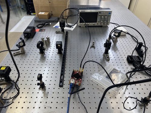
|
| Attachment 2: IMG_6754.jpg
|
|
| Attachment 3: IMG_6755.jpg
|
|
|
135
|
Tue Jun 27 15:18:26 2023 |
Pamella | Update | FLIR | New data collection |
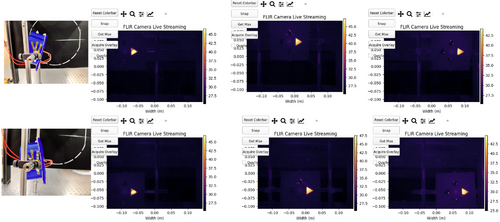
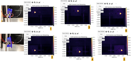
Yesterday, I did a new data collection. I could get a better data in this time and I realized than I need use some angle on the reflector for got a better shot. I need do that because the FLIR camera just is able to get the triangle shape for complete if I keep exactly in same line for center point on the camera but for the data now I need move the refletor to go up and go down. So wasn't working very well if I keep the reflector without angle.
Now I am using the refletor with a angle. In the more high part I turn the mask for look the table and in the lower part I turn the mask to look up. I attached a photo below for this configuration.
Also the processes to get the data was the same than I using last time, the only diference is now I just moved the pillar after get data for high position and lower position for the same reference point on the triangle shape.
Note: In most data it is impossible to keep the same parameter for current, voltage and temperature. Most have a small variation but not a big difference. For example: I got the temperature in the first position 46.8 °C and in the second position I got 47.1 °C, it's just an example. It's just so we know that we don't have the exact same parameters all the time. In my opinion this is not a problem because it is just a small variation.
- 09:35 am: Turned on the device (current on). I wanted for 30 minutes before start get data.
- 10:05 am: Started taking snap on position one (Reference point: -0.10, 0.050). Parameters:0.11A,1.7V,46.8°C
- I took four snap on the same position for compare after on data analyzes. I just wanted one minute break between the snaps. I did the same for every position.
- 10:15 am: Started taking snap on position two (Reference point:-0.10,-0.050 ). Parameters: 0.11A,1.7V,47.1° C
- 10:22 am: Started taking snap on position three (Reference point:0.00 ,0.050). Parameters: 0.11A,1.6V,48.1°C
- 10:26 am: Started taking snap on position four (Reference point: 0.00,-0.050). Parameters:0.11A,1.6V,48 °C
- 10:32 am: Started taking snap on position five (Reference point: 0.05,-0.050). Parameters:0.11A, 1.6V, 48°C
- 10:37 am: Started taking snap on position six (Reference point: 0.05,0.050). Parameters: 0.11A,1.7V,47.6 °C
- We can see in the photos attached below every position also I am working in the analyzes.
|
| Attachment 1: FLIR_data.002.jpeg
|
|
| Attachment 2: FLIR_data_2.002.jpeg
|
|
|
139
|
Fri Jun 30 15:57:28 2023 |
Pamella | Update | FLIR | Data and python code update |
Updates: Problems with the emission intensity and python code.
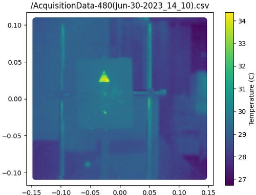
- Yesterday I was working on get data from FLIR reflector but unfortunately we got some problems:
- I realized than if I move the reflector a to left or right the screen doesn't get data very well(I attached a photo below). This is a problem because our idea is have the same type of emission every part on screen. Tyler and I worked to tried fix that but don't had success.
- Dr. Richardson gave me the idea to move the FLIR camera to left or right (The same happens if I move up and down) and keep the refletor on the same position every time but unfortunately we got the same problem, the screen doesn't get data very well(I attached a photo below). Now I am working to tried fix that.
- Also I was able to work on the code to isolate the triangle shape for analyzes, I attached the image for that below.
|
| Attachment 1: isolation1-2.jpg
|
|
| Attachment 2: AcquisitionImage(Jun-29-2023_18_27)_(1).jpg
|
_(1).jpg.png)
|
| Attachment 3: AcquisitionImage(Jun-29-2023_18_38).jpg
|
.jpg.png)
|
| Attachment 4: AcquisitionImage(Jun-29-2023_18_39).jpg
|
.jpg.png)
|
|
140
|
Fri Jun 30 16:43:14 2023 |
Pamella | Update | FLIR | Updates: Small moving the FLIR camera |
[Pamella]
Today, I was able to make some adjustments to the FLIR camera angle, suggested by Dr. Richardson, and we got small possible movements keeping the same pattern in the shapes of the triangles. I have attached photos below. I was able to move left and right as well as up and down and it worked in four points that I marked on the table.
The only problem is that it only worked on a part of the screen, if I try to place it farther to the right or to the left, we are back to the same problem as yesterday.
|
| Attachment 1: AcquisitionImage(Jun-30-2023_16_23)_(3).jpg
|
_(3).jpg.png)
|
| Attachment 2: AcquisitionImage(Jun-30-2023_16_23)_(1)(1).jpg
|
_(1)(1).jpg.png)
|
| Attachment 3: AcquisitionImage(Jun-30-2023_16_24).jpg
|
.jpg.png)
|
| Attachment 4: AcquisitionImage(Jun-30-2023_16_22)_(1)(1).jpg
|
_(1)(1).jpg.png)
|
| Attachment 5: AcquisitionImage(Jun-30-2023_16_22)_(1).jpg
|
_(1).jpg.png)
|
|
143
|
Mon Jul 3 18:38:13 2023 |
Pamella | Update | FLIR | FLIR project |
[Pamella]
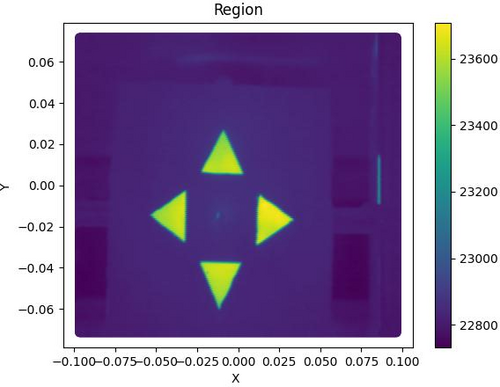
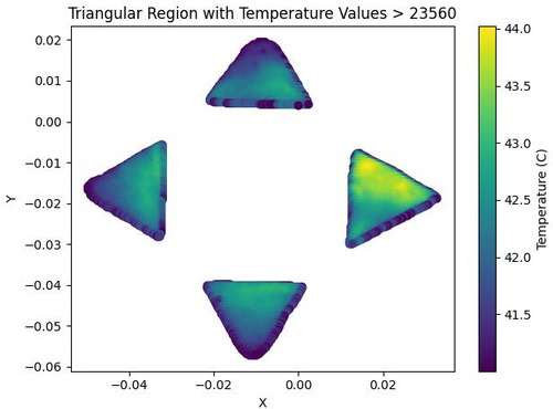
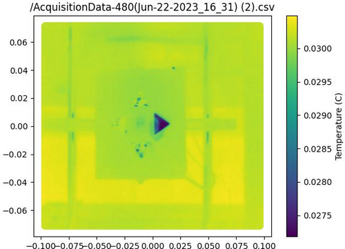
- I was able to work on the python code to do analysis on the FLIR-Reflector data.
- I could plot images of total area (Tyler help me on that) with csv file and also could have isolation area for triangles. I have attached examples below. Just for now the images are of different data, so there are some differences in the shapes.
- I'm working on getting a complete analysis code to work with the different positions of the triangles and to be able to do out the statistical analysis.
- Also we keeping have problem to get good data if when we move the camera or the reflector on horizontal or vertical position. I am working a some ideas for that.
|
| Attachment 1: Region.jpg
|
|
| Attachment 2: triangular_region_temperature-2.jpg
|
|
| Attachment 3: heatmap.jpg
|
|
| Attachment 4: isolation1-4.jpg
|
|
|
144
|
Tue Jul 4 15:35:38 2023 |
Pamella | Update | FLIR | FLIR - reflexion problem |
| [Pamella]
I was testing all the positions we need to cover when moving the FLIR camera or the reflector. I tried to find out more about the problem so I tested the position without the mask, just with the old bridge and I got the same problems, in the middle of the screen we have a very good image but if we move we have the visualization problem and we don't see the reflection very well (intensity, emissivity) in FLIR.
For this test I used very low current (0.04 A) for keep everything safety.
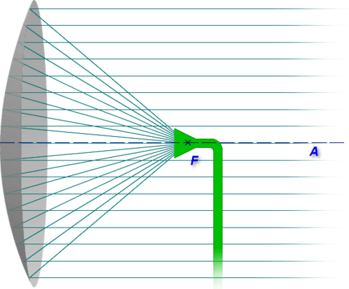
I also think that problem is not in the focal point of the reflector because we can see very well in the center of the screen, but maybe it is because in the parabolic reflector the reflection in the focal point is "extremely" straight, so for you to see the reflection in this point you need keep close to the middle of the screen, to see around the reflector, at the extremes, we need to change the position for the cable or the light to "change" how the flashes of light reflect and thus achieve exactly the position on the camera. It is something like the sketch/ photo attached below. |
| Attachment 1: AcquisitionImage(Jul-03-2023_14_29).jpg
|
.jpg.png)
|
| Attachment 2: AcquisitionImage(Jul-03-2023_14_31).jpg
|
.jpg.png)
|
| Attachment 3: AcquisitionImage(Jul-03-2023_14_49).jpg
|
.jpg.png)
|
| Attachment 4: Caderno_sem_título_(26)-2.jpg
|
-2.jpg.png)
|
| Attachment 5: parabol1.print.png
|
|
|
146
|
Wed Jul 5 16:02:12 2023 |
Aiden | Update | Clean & Bake | Clean and Bake batch 14 Bagging |
| Bagged and Tagged the 2.75" copper gaskets from Batch 14 and placed them into the clean room on the work bench. |
|
147
|
Thu Jul 6 13:34:48 2023 |
Pamella, Shane, Julian, Aiden | Update | Cleanroom | cleaning and particle count |
|
[Pamella, Julian, Aiden, and Shane]
|
|
149
|
Thu Jul 6 18:03:19 2023 |
Pamella | Update | FLIR | FLIR project - New configuration |
[Pamella]
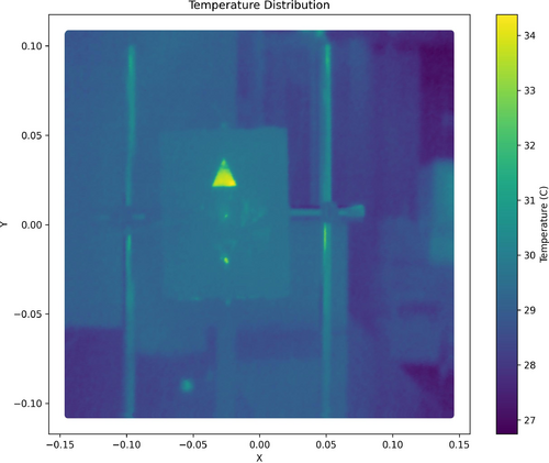
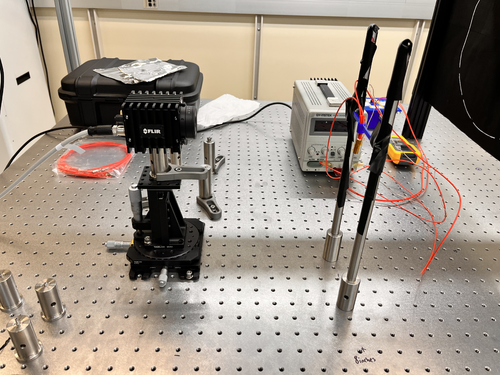
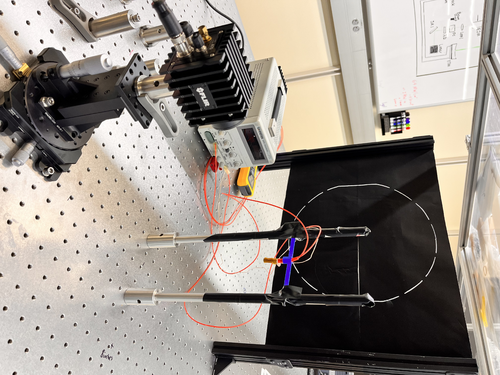
Cao suggested using the project without the reflector and mask because in this case we probably got good images around the screen. So I started this yesterday and today I started to get some data to see the stabilization position and check how the parameters fluctuated. I was looking and taking snaps for an hour and a half. I'll repeat this one more time to make sure we have enough data to do analysis.
To do: The next step is to start collecting data by moving the camera FLIR and covering all six positions on the screen (2x3). Also Aiden is on hand to help and is going to make a new 3D print bridge to have good heater support.
I attached a image for the new configuration below and a snap data. |
| Attachment 1: IMG_8193.jpeg
|
|
| Attachment 2: IMG_8183.jpeg
|
|
| Attachment 3: AcquisitionImage(Jul-06-2023_17_18)_(1).jpg
|
_(1).jpg.png)
|
| Attachment 4: region_temperature1.jpg
|
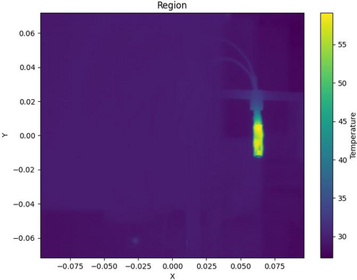
|
|
150
|
Fri Jul 7 15:11:39 2023 |
Aiden | Update | VAC | VAC System Heating Update |
The temperature of the flange connecting to the turbo pump after reaching equilibrium is 74 degC. This means that it is safe to proceed with raising the temperature from 120 degC to 150 degC.
Raised the set temperature of the chamber from 120 degC to 150 degC in 15 deg steps.
|
|
151
|
Sat Jul 8 14:26:17 2023 |
Pamella | Update | FLIR | Data with the new configuration without the mask and reflector. |
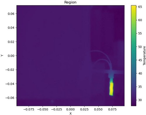
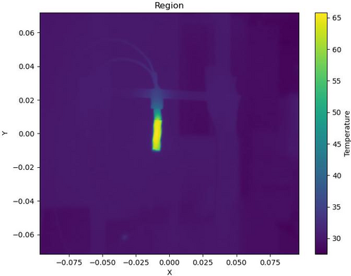
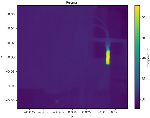
| [Pamella]
I started collecting data by moving the camera FLIR and covering all six positions on the screen (2x3). I was looking and taking snaps for more than one hour and a half. I'll repeat this one more time to make sure we have enough data to do analysis.
I attached snap data below. This images is processed on python code. |
| Attachment 1: region2-3.jpg
|
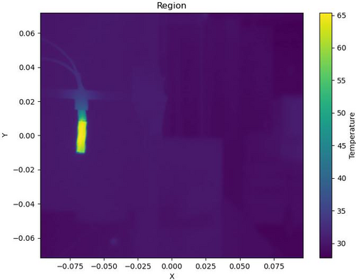
|
| Attachment 2: region3-2.jpg
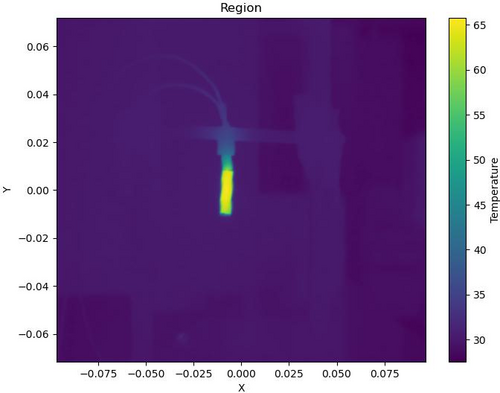
|
|
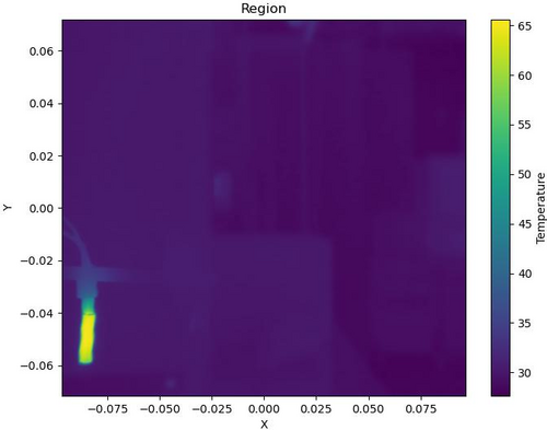
| Attachment 3: region4.jpg
|
|
| Attachment 4: region5.jpg
|
|
| Attachment 5: region6.jpg
|
|
| Attachment 6: region_temperature1-2.jpg
|
|
|
152
|
Mon Jul 10 13:23:23 2023 |
Aiden | Update | VAC | VAC System Heating Update |
Checked on the system today.
The flange on the turbo pump has reached an equilibrium temperature of 87 degC when set at 150 degC. While the main body of the chamber has reached an equilibrium temperature of 142 degC.
|
|
153
|
Thu Jul 13 14:56:43 2023 |
Aiden | Update | VAC | VAC System Heating Update |
Checked on the vacuum system today to change the PID controls back to their default values in order to try and get the temperature of the cross in front of the turbo pump higher. Currently it is sitting at 90 degC before changing the controls. While the main body is at 146 degC.
Will update again tomorrow on new equilibrium with the default PID settings.
|
|
154
|
Thu Jul 13 15:31:21 2023 |
Jon | Update | General | Ant traps placed around lab |
In response to reports that ants have been observed in the lab, I placed five ant bait traps around the room today. Each is sitting on the floor on top of a piece of aluminum foil, in areas unlikely to be inadvertently stepped on. They contain liquid which will spill out if picked up, so please take care not to disturb them. |
|
155
|
Thu Jul 13 16:59:03 2023 |
Jon | Update | General | Ant traps placed around lab |
Update: After seeing the strong response to the first set, I redistributed them to the hottest spots and added one more trap.
| Quote: |
|
In response to reports that ants have been observed in the lab, I placed five ant bait traps around the room today. Each is sitting on the floor on top of a piece of aluminum foil, in areas unlikely to be inadvertently stepped on. They contain liquid which will spill out if picked up, so please take care not to disturb them.
|
|