| ID |
Date |
Author |
Type |
Category |
Subject |
|
653
|
Fri Oct 10 14:40:23 2025 |
Xuesi Ma | Update | VAC | Pressure gauge Swap |
[Tyler, Ma]
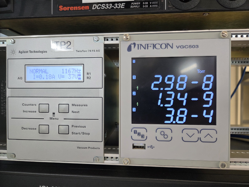
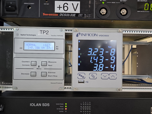
We suspect a pressure gauge problem. The electronic unit of the main chamber pressure gauge and the electronic unit of the RGA chamber pressure gauge are swapped.
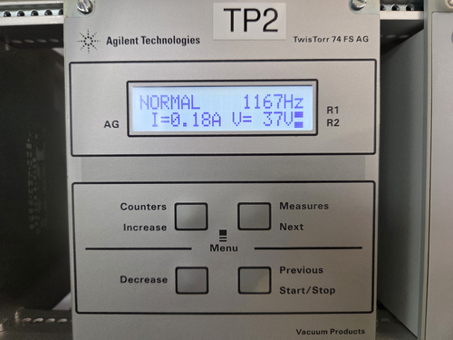
Power and current draw aren't high for the turbo pump.
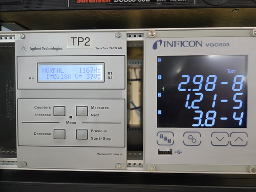
Before opening the gate valve, the pressure in the Main chamber is 2.98e-8 Torr, RGA Chamber 1.21e-5 Torr
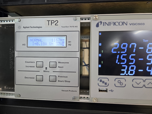
After opening the gate valve (not fully open), the pressure in the Main chamber is 2.97e-8 Torr, RGA Chamber 1.55e-9 Torr. Note: the HV sensor suddenly turned on and the reading jumped to -9 Torr
Opening the gate valve a bit more, the pressure in the Main chamber is 2.98e-8 Torr, RGA Chamber 1.34e-9 Torr.
After switching the electronic unit, the pressure in the Main chamber is 3.23e-8 Torr, RGA Chamber 1.43e-9 Torr.
Gate Valve fully opened at 16:01 Oct 24, 2025 |
| Attachment 1: 1433.jpg
|
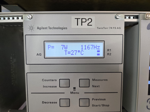
|
| Attachment 2: 1434.jpg
|
|
| Attachment 3: 1517.jpg
|
|
| Attachment 4: 1519.jpg
|
|
| Attachment 5: 1520.jpg
|
|
| Attachment 6: 1521.jpg
|
|
|
656
|
Thu Oct 23 11:09:16 2025 |
Xuesi Ma | Update | Measuring Noise in Interferometer | Scatter Noise Model |
DetChar meeting presentation |
|
662
|
Thu Nov 20 12:40:47 2025 |
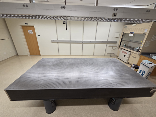
Xuesi Ma | Infrastructure | General | Room 1125 Optical Table |
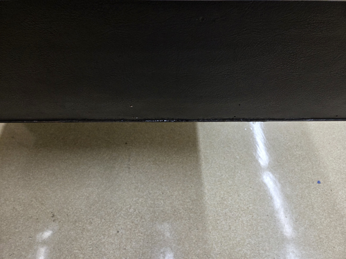
Cleaned off the tapes on the optical table with acetone. |
| Attachment 1: 1651.jpg
|
|
| Attachment 2: 1650.jpg
|
|
|
669
|
Thu Jan 15 13:52:55 2026 |
Xuesi Ma | Update | TCS | FROSTI A# Reflector Update |
| Slides |
|
389
|
Fri Jun 28 10:43:13 2024 |
Xuejun | Update | Cleanroom | Frosti |
| [Xuejun, Tyler]
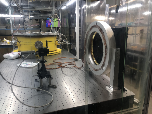
We moved Frosti into the cleanroom and debugged it to make sure everything was working. One of the DB25 pins broke off at the connector for element 1 so it needed to be recrimped. Element 6 short circuited but fixed with adjustment to the heater power pin position. We connected the power and sensor connectors to the power box and recalibrated the RTD sensors.
|
| Attachment 1: frosti.jpg
|
|
| Attachment 2: chassis.jpg
|

|
|
396
|
Mon Jul 8 10:39:14 2024 |
Xuejun | Update | FLIR | Average Temperature Profile |
After taking data for each of the individual heater elements, I imported them into python and overlayed them to produce an average temperature profile. I rotated the 7 of the elements to align with element 1's profile and averaged them out. By setting the range to 28C - 33C (this gave the best visibility of the heating pattern) it gave the profile attached. |
| Attachment 1: Average-Temperature-Profile.pdf
|

|
|
421
|
Tue Aug 6 13:07:07 2024 |
Xuejun | Update | Interferometer Simulations | |
| [Xuejun]
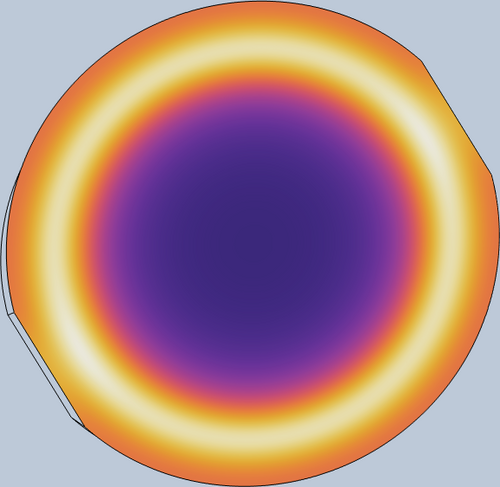
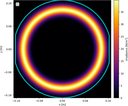
The width and location of the measured in-air change in temperature profile has been determined to be 0.045m and 0.137m respectively. Subsequently, a fake irradiance profile was able to be generated that best resembled what the actual irradiance profile could be using this information for testing in COMSOL. The generated irradiance profile that output the most similar change in temperature profile as the measured in-air profile has been included as well as the change in temperature profile it produced on the blackbody screen "test mass" model in COMSOL. |
| Attachment 1: Thermal_model_image.png
|
|
| Attachment 2: generated_irradiance_profile.png
|
|
|
641
|
Tue Sep 9 12:01:38 2025 |
Tyler, Ma | Update | | |
| Slides |
|
235
|
Mon Oct 9 11:29:37 2023 |
Tyler | Update | Electronics | PSD/CSD Plot Updates |
| Continuing from Sophia's SURF Project this summer: Plotting the Power-Spectral Densities (PSDs) and Cross-Spectral Densities of two signals.
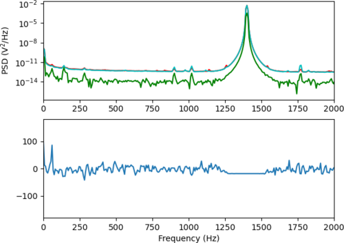
A continued issue that has been observed in the plots is the random "jump" of one PSD curves. Below, a 1.4 kHz signal is driven with a magnitude of 0.7 Vpp, and connected to the two output ports of the Red Pitaya via an SMC T-Adapter. At the moment, I anticipate that this bug might have something to do with the Real-Time GUI code being used, since this hasn't been observed when running the calculations without it (see below). |
| Attachment 1: Screenshot_2023-10-09_at_11.20.25_AM.png
|

|
| Attachment 2: welch_csd-2.png
|
|
|
243
|
Mon Oct 23 11:28:05 2023 |
Tyler | Update | Cameras | FLIR Camera Code Updates |
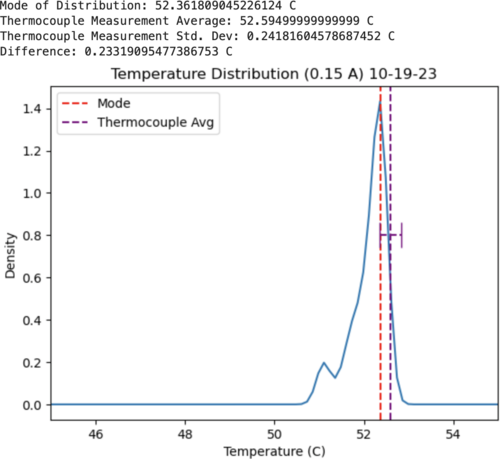
| The past week I've been spending time going through the FLIR code on gitlab. Initially, it had appeared that our measurements with the camera had differed about 2 degrees C from what the thermocouple was giving (Ref ELOG 181). Upon inspection of the FLIR streaming code, I noticed a few issues:
1. The emissivity value wasn't set correctly (was 0.999 originally, should be about 0.95).
2. The ambient temperature was set to about 21.6 C (71 F).
3. The distance given before was about an inch off from what I measured.
These three parameters all must be manually specified to calculate the temperature values, and are what I assume caused the larger temperature difference seen before. I've attached a new set of measurements that I took below, where 6 images were taken by the camera, looking at a heating source with a current of 0.15 A being driven. The difference between the camera and the thermocouple were much smaller, as seen below. I'd still like to take a few more measurements to solidify that this has rectified the issue, but at the moment it seems this is working much better.
Images at: https://drive.google.com/drive/folders/1VDvZ1rfEGWsHq1AgG-chde3Cd8Do_piD?usp=sharing |
| Attachment 1: Screenshot_2023-10-23_at_11.06.04_AM.png
|
|
|
249
|
Mon Oct 30 11:03:56 2023 |
Tyler | Update | Scripts/Programs | |
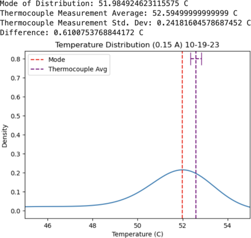
FLIR: After some adjustments, the plot generated from the FLIR measurements look much more symmetric (see attachment). There are more included grid points, which smooths out the curve as compared to last week.
Red Pitaya: It looks like a new OS update was released for the RP, which includes a new Python API (was previously only available in C). I'm going to try and update the one we have currently running in lab.
|
| Attachment 1: Screenshot_2023-10-23_at_12.39.05_PM.png
|
|
|
255
|
Mon Nov 6 11:29:24 2023 |
Tyler | Update | Electronics | Preliminary RTD Calculations, RP Software Update |
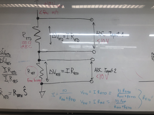
Preliminary RTD calculations are shown below, given an input of 10 V and desiring a few mA of current. It looks like R_ref should be at least 1 kOhm (refer to plots/circuit below), keeping in mind we need to have <10 V input for the ADC.
RP: The Red Pitaya Software was updated to OS 2.00. All examples on the RP website should run without issue. |
| Attachment 1: cvt.png
|

|
| Attachment 2: VvC.png
|

|
| Attachment 3: IMG_7471.jpg
|
|
|
264
|
Mon Nov 13 11:07:50 2023 |
Tyler | Update | VAC | RTD Analysis |
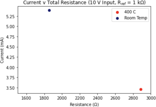
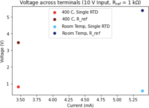
After initial analysis from last week on a single RTD, I then extended to looking at all 8 in series with R_ref (set to 1 kOhm). Shown below are the edge cases for the setup:
- RTDs are all at ambient lab temperature. This would correspond to a minimum resistance value.
- RTDs all read out 400 C. This gives the maximum resistance value.
The results show that indeed only a few mA of current is drawn even at room temperature (a little above 5.5 mA), and this will continue to decrease with increasing temperature. The voltage across a single terminal, at a maximum, is only about 5.4 V. |
| Attachment 1: Screenshot_2023-11-13_at_11.05.45_AM.png
|
|
| Attachment 2: Screenshot_2023-11-13_at_11.06.04_AM.png
|
|
|
271
|
Mon Nov 20 10:10:50 2023 |
Tyler | Configuration | Electronics | RTD Logic/Schematic Diagrams |
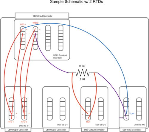
Below are a basic diagram of what the RTD measurement circuit logically looks like and an example schematic of the actual wiring. The schematic wiring will be placed internally into a chassis, connected to the RTDs via DB25 cable.
Note: The DB25 Breakout Board connector is Female, not Male. |
| Attachment 1: FIN_RTD_circuit.png
|

|
| Attachment 2: Sample_Circuit_Schematic.png
|
|
|
274
|
Tue Nov 21 14:47:24 2023 |
Tyler | Update | Lore | 1129 Workbench Assembly Update 1 |
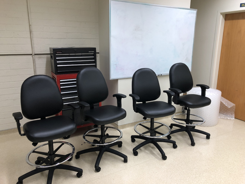
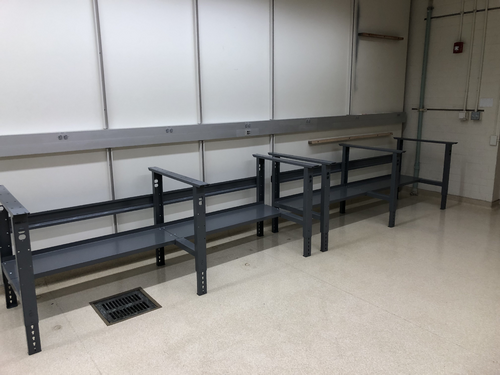
[Tyler, Shane, Mohak, Cynthia, Luke, Michael, Luis]
Started assembly of the workbench equipment today. We completed the stools, and have constructed the frames of each workbench. All that needs to be added are the tabletops and the top shelves, which will be done on Monday. |
| Attachment 1: IMG_7569.jpg
|
|
| Attachment 2: IMG_7568.jpg
|
|
|
278
|
Mon Nov 27 14:22:30 2023 |
Tyler | Update | Lore | 1129 Assembly Update |
| [Tyler, Michael, Luke, Cynthia]
The tabletops have been attached to the workbench frames. Unfortunately, one of the tabletops came out of the box with a large scratch and small dent in the middle. One of the electric top shelves is ready to be attached to the undamaged table, but the other is yet to be opened. Assembly will be completed Wednesday morning.
|
| Attachment 1: IMG_7669.jpg
|
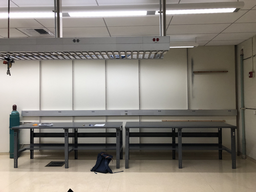
|
| Attachment 2: IMG_7668.jpg
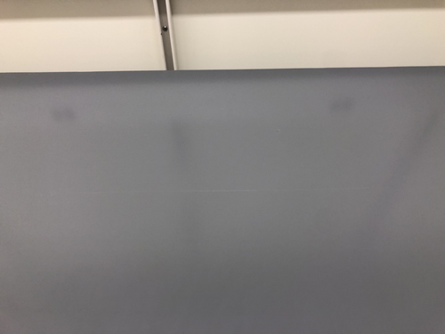
|
|
|
281
|
Thu Nov 30 13:50:32 2023 |
Tyler | Update | Lore | Workbench Assembly Completed |
| [Tyler, Luke, Aiden]
The workbenches are now completely assembled and put into their final places. Additionally, the tool chest has been moved.
|
| Attachment 1: IMG_7686.jpg
|
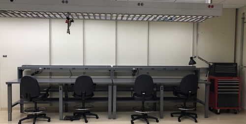
|
|
300
|
Tue Jan 9 12:08:59 2024 |
Tyler | Configuration | Electronics | RTD Readout Chassis Update |
Below is the current state of the RTD readout chassis wiring. Initial continuity tests seem good, will run through one more time to confirm.
| Quote: |
The custom front and rear panels for the RTD readout chassis arrived last Friday. I installed them in the chassis frame to check their fit. They fit very well, so all that now remains is to complete the internal wiring and test the connections.
The chassis panel designs are archived to LIGO-D2300452 and LIGO-D2300453.
| Quote: |
|
Below are a basic diagram of what the RTD measurement circuit logically looks like and an example schematic of the actual wiring. The schematic wiring will be placed internally into a chassis, connected to the RTDs via DB25 cable.
Note: The DB25 Breakout Board connector is Female, not Male. |
|
|
| Attachment 1: IMG_8105.jpg
|
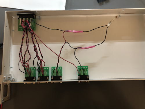
|
|
305
|
Tue Jan 16 12:20:21 2024 |
Tyler | Configuration | Electronics | RTD Readout Chassis Update 2 |
I performed another continuity test on the RTD chassis wiring, and everything seems to be set up correctly. The chassis should be ready for installation.
| Quote: |
Below is the current state of the RTD readout chassis wiring. Initial continuity tests seem good, will run through one more time to confirm.
| Quote: |
The custom front and rear panels for the RTD readout chassis arrived last Friday. I installed them in the chassis frame to check their fit. They fit very well, so all that now remains is to complete the internal wiring and test the connections.
The chassis panel designs are archived to LIGO-D2300452 and LIGO-D2300453.
| Quote: |
|
Below are a basic diagram of what the RTD measurement circuit logically looks like and an example schematic of the actual wiring. The schematic wiring will be placed internally into a chassis, connected to the RTDs via DB25 cable.
Note: The DB25 Breakout Board connector is Female, not Male. |
|
|
|
| Attachment 1: IMG_8146.jpg
|
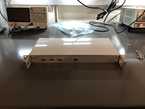
|
| Attachment 2: IMG_8147.jpg
|
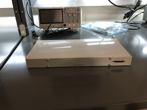
|
|
310
|
Tue Jan 23 12:17:41 2024 |
Tyler | Update | Electronics | RTD Chassis |
After updating the wiring in the RTD Chassis, a signal is now seen at each ADC input. However, there seems to be a discrepancy between the voltages I measured out with the multimeter (see below). Next steps include:
- Finish final debugging
- Calibrate ADC inputs with known voltage source (likely to use DAC).
Voltage Readings:
RTD 1: 0.576 V
RTD 2: 0.578 V
RTD 3: 0.598 V
RTD 4: 0.563 V
RTD 5: 0.477 V
RTD 6: 0.463 V
RTD 7: 0.456 V
RTD 8: 0.491 V
Reference Resistor: 5.463 V
Total Voltage: 9.665 V |
| Attachment 1: rtd_updated_circuitry.jpg
|
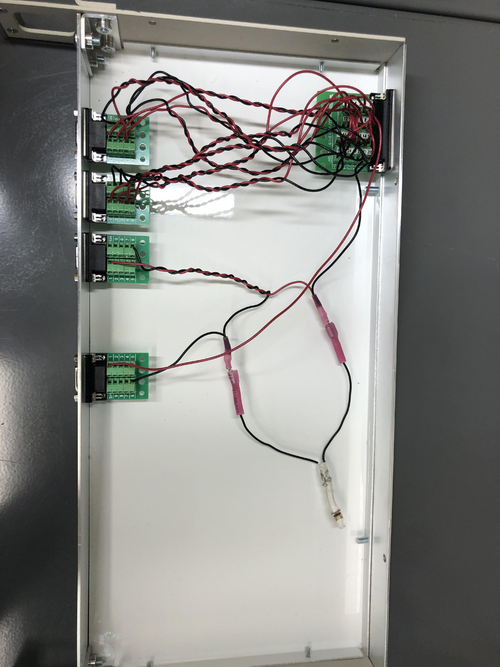
|
|
311
|
Tue Jan 30 11:36:19 2024 |
Tyler | Update | Electronics | RTD Chassis |
| Quote: |
After updating the wiring in the RTD Chassis, a signal is now seen at each ADC input. However, there seems to be a discrepancy between the voltages I measured out with the multimeter (see below). Next steps include:
- Finish final debugging
- Calibrate ADC inputs with known voltage source (likely to use DAC).
Voltage Readings:
RTD 1: 0.576 V
RTD 2: 0.578 V
RTD 3: 0.598 V
RTD 4: 0.563 V
RTD 5: 0.477 V
RTD 6: 0.463 V
RTD 7: 0.456 V
RTD 8: 0.491 V
Reference Resistor: 5.463 V
Total Voltage: 9.665 V |
After further modification of the RTD readout chassis (i.e. adding resistors, placing reference resistor in front of RTDs), here are the following direct measurements:
RTD 1: 0.484 V
RTD 2: 0.486 V
RTD 3: 0.503 V
RTD 4: 0.474 V
RTD 5: 0.495 V
RTD 6: 0.483 V
RTD 7: 0.476 V
RTD 8: 0.510 V
Reference: 5.847 V
Here are the Cymac signal readings:
RTD 1: 74
RTD 2: 67
RTD 3: 73
RTD 4: 45
RTD 5: 82
RTD 6: 75
RTD 7: 70
RTD 8: 71
Reference: 884
The one (possible) discrepancy here is the readout for RTD 4 via Cymac, since it's signal reading is ~30 counts lower than the others. I do not believe this is a wiring issue due to the direct measurements taken. |
|
323
|
Tue Feb 13 11:54:45 2024 |
Tyler | Configuration | FLIR | In-Air Optical Test Configuration |
Below is the proposed schematic for FROSTI optical testing, chosen so enough space is allotted for prototype assembly.
Steps to be taken include:
- Reconstruct FLIR staging apparatus
- Move test mass stand-in to cleanroom
- Mark FLIR camera position on cleanroom optical table at correct distance
- Run ethernet cable into cleanroom
- Move FLIR aside to allow for more assembly space
- Upon assembly completion, reposition FLIR onto optical table again
Tentative plan is to begin setup early next week. |
| Attachment 1: In-air_optical_test_sketch.png
|
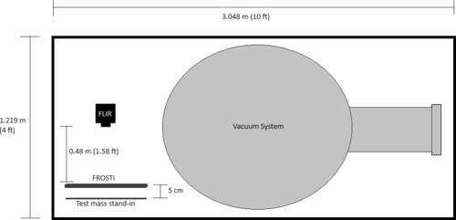
|
|
324
|
Tue Feb 13 12:26:23 2024 |
Tyler | Update | Interferometer Simulations | BS Code Update |
I reproduced Cao's CE beamsplitter code (see below for example plots). I received the current info on the beamsplitter parameters for A+ and A# from GariLynn also. The next steps are to perform a similar power loss analysis on the anticipated A# beamsplitter. |
| Attachment 1: thickness1.pdf
|

|
| Attachment 2: bs_opd_homloss_h6cm_w2cm.pdf
|

|
|
331
|
Tue Feb 20 11:31:49 2024 |
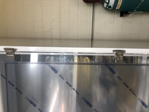
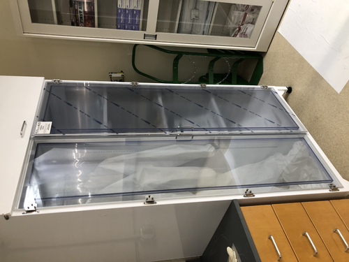
Tyler | Update | Cleanroom | Garment Cabinet Door Replacement |
| [Luis, Luke, Pooyan, Tyler]
The replacement door for the HEPA garment cabinet arrived last week, and was installed on Thursday. However, it looks like there's a small gap between the door and where the hinge is attached to the cabinet frame. No screws were provided with the replacement door. If we want to perform any adjustments, we have to be very careful; the screws break very easily.
|
| Attachment 1: image_67190529.JPG
|
|
| Attachment 2: image_67177473.JPG
|
|
|
338
|
Fri Feb 23 18:03:27 2024 |
Tyler | Update | FLIR | Optical Test Setup in Cleanroom |
| [Tyler, Xuesi]
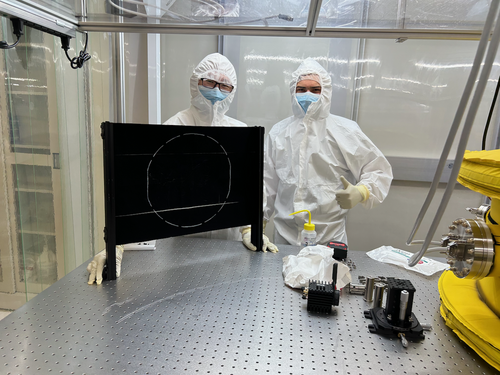
The FLIR and test mass stand-in have been transferred into the cleanroom. A software test will be run as soon as we get an ethernet cable long enough to reach into the cleanroom where the camera is set up. Once this is finished, the FLIR will be moved aside for construction of the FROSTI! When completed, the camera will be placed back into position for in-air optical testing.
|
| Attachment 1: IMG_0941.png
|
|
|
344
|
Wed Feb 28 12:02:08 2024 |
Tyler | Update | General | Resistors for Heater Elements Update |
| Power Res (Ohm) RTD Res (Ohm)
Heater 1= 72.8; 80.6
Heater 2= 69.5; 80.8
Heater 3= 70; 83.2
Heater 4= 70.6; 78.7
Heater 5= 69.9; 80.6
Heater 6= 71.1; 78.2
Heater 7= 68.5; 76.8
Heater 8= 70.1; 82.8
| Quote: |
| Power Res (Ohm) RTD Res (Ohm)
Heater 1= 73.6; 81.8
Heater 2= 70.4; 82.1
Heater 3= 71; 84.5
Heater 4= 71.5; 80
Heater 5= 70.5; 81.7
Heater 6= 72; 79.4
Heater 7= 69.2; 78.2
Heater 8= 71.1; 84.2 |
|
|
345
|
Wed Feb 28 17:49:18 2024 |
Tyler | Update | TCS | FROSTI Assembly - Days 2-3 |
| [Aiden, Jon, Luis, Luke, Michael, Tyler]
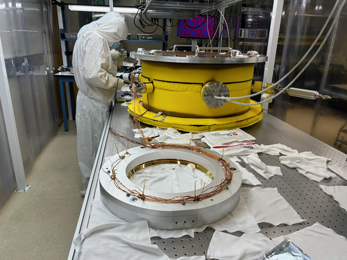
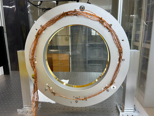
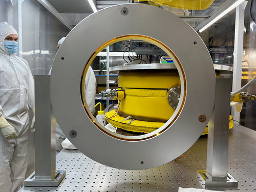
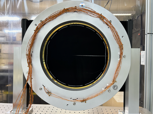
FROSTI assembly was completed today. The RTD and power wires were terminated at the DB-25 connectors and the legs were put on. It is currently placed in front of the stand-in test mass (~5 cm away). The FLIR has also been moved back to it's nominal position. As of now, it appears there are some shorts within the power cabling. This will be a focus of tomorrow's work.
| Quote: |
| [Jon, Tyler, Luis, Luke, Mohak, Cynthia, Michael, Aiden]
FROSTI assembly began today. After a final set of RGA scans were taken, the vacuum chamber was vented and the reflectors were removed. The chamber was then resealed and pumped down again.
Today we completed the installation of the Macor hardware and heater elements between the two reflector halves. Tomorrow we will route, bundle, and terminate the power and sensor cables. |
|
| Attachment 1: IMG_0947.png
|
|
| Attachment 2: IMG_0956.png
|
|
| Attachment 3: IMG_0957.png
|
|
| Attachment 4: IMG_0959.png
|
|
|
347
|
Wed Mar 6 09:57:52 2024 |
Tyler | Update | TCS | FROSTI Wiring |
Upon finishing the FROSTI assembly last week, we ran into some electrical issues. An electrical short was found between two of the d-sub pins (2 and 8). It appears that the pins were somehow coming into contact with the aluminum surrounding them. This was causing the power supply to trip. The issue was seemingly fixed by adjusting the positioning of the cabling leading out of the reflector. When handling the device in the future, please make sure to keep the wiring as undisturbed as possible. The setup is rather fragile, and moving the cabling around could potentially reintroduce a short like this. |
|
349
|
Tue Mar 19 10:55:30 2024 |
Tyler | Update | FLIR | In-Air Optical Test |
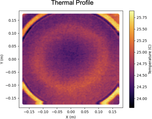
| Below is an image I took using the FLIR just before leaving for the LVK meeting. The profile is roughly what we would expect (annular). Any distortions seen are likely from the screen not being completely parallel to the plane of the FroSTI (i.e. the screen slightly bends in various locations). Next step: In-vacuum test at CIT. |
| Attachment 1: FroSTI_Thermal_Profile.png
|
|
|
351
|
Thu Mar 21 16:56:42 2024 |
Tyler | Update | DAQ | RTD Parameter Calibration |
| [Jon,Tyler]
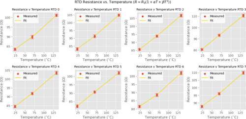
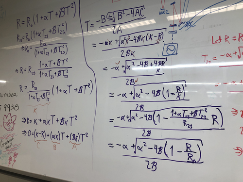
We noticed that the RTD temperature readings given on the Cymac were off, and traced the issue to miscalibration in the relationship between the resistance and temperature of each RTD (Callendar-Van Dusen eqn). Below is the table of values inferred from independent measurements of temperature and resistance to rectify this problem. This data was then fitted to better determine the coefficients present in the temperature-resistance relation:
R_0 (ohm) Alpha Beta
RTD 0 80.8674 0.001315 4.273e-6
RTD 1 79.5704 0.001887 3.7873e-6
RTD 2 81.7334 0.002014 2.1724e-6
RTD 3 74.3060 0.003677 3.6022e-8
RTD 4 81.1350 0.001761 2.3598e-6
RTD 5 77.9610 0.002423 -7.5192e-7
RTD 6 78.7980 0.001373 6.2909e-6
RTD 7 83.8616 0.001890 3.3529e-6 |
| Attachment 1: RTD_Calib-2.png
|
|
| Attachment 2: IMG_8569.jpg
|
|
|
354
|
Mon Mar 25 10:55:33 2024 |
Tyler | Update | DAQ | RTD Parameter Calibration |
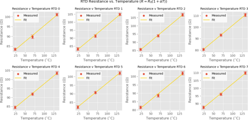
| Refitted RTD calibration, neglecting quadratic term:
R_0 (ohm) Alpha (1/C)
RTD 0 79.3962 0.002031
RTD 1 78.2874 0.002530
RTD 2 80.9775 0.002381
RTD 3 74.2947 0.003684
RTD 4 80.3199 0.002157
RTD 5 78.2106 0.002297
RTD 6 76.6825 0.002438
RTD 7 82.6645 0.002458
Measurements taken can be found here. An uncertainty of 1 C was assumed for temperature.
| Quote: |
| [Jon,Tyler]
We noticed that the RTD temperature readings given on the Cymac were off, and traced the issue to miscalibration in the relationship between the resistance and temperature of each RTD (Callendar-Van Dusen eqn). Below is the table of values inferred from independent measurements of temperature and resistance to rectify this problem. This data was then fitted to better determine the coefficients present in the temperature-resistance relation:
R_0 (ohm) Alpha Beta
RTD 0 80.8674 0.001315 4.273e-6
RTD 1 79.5704 0.001887 3.7873e-6
RTD 2 81.7334 0.002014 2.1724e-6
RTD 3 74.3060 0.003677 3.6022e-8
RTD 4 81.1350 0.001761 2.3598e-6
RTD 5 77.9610 0.002423 -7.5192e-7
RTD 6 78.7980 0.001373 6.2909e-6
RTD 7 83.8616 0.001890 3.3529e-6 |
|
| Attachment 1: RTD_Calib_nobeta.png
|
|
|
355
|
Tue Mar 26 13:51:56 2024 |
Tyler | Update | DAQ | RTD Parameter Calibration |
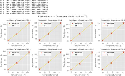
Another re-fit, but this time the quadratic coefficient (beta) is set to 1.003e-6:
R_0 (ohm) Alpha (1/C)
RTD 0 79.7386 0.001863
RTD 1 78.6248 0.002359
RTD 2 81.3254 0.002211
RTD 3 74.6127 0.003509
RTD 4 80.6652 0.001988
RTD 5 78.5450 0.002127
RTD 6 77.0144 0.002268
RTD 7 83.0204 0.002288
| Quote: |
| Refitted RTD calibration, neglecting quadratic term:
R_0 (ohm) Alpha (1/C)
RTD 0 79.3962 0.002031
RTD 1 78.2874 0.002530
RTD 2 80.9775 0.002381
RTD 3 74.2947 0.003684
RTD 4 80.3199 0.002157
RTD 5 78.2106 0.002297
RTD 6 76.6825 0.002438
RTD 7 82.6645 0.002458
Measurements taken can be found here. An uncertainty of 1 C was assumed for temperature.
| Quote: |
| [Jon,Tyler]
We noticed that the RTD temperature readings given on the Cymac were off, and traced the issue to miscalibration in the relationship between the resistance and temperature of each RTD (Callendar-Van Dusen eqn). Below is the table of values inferred from independent measurements of temperature and resistance to rectify this problem. This data was then fitted to better determine the coefficients present in the temperature-resistance relation:
R_0 (ohm) Alpha Beta
RTD 0 80.8674 0.001315 4.273e-6
RTD 1 79.5704 0.001887 3.7873e-6
RTD 2 81.7334 0.002014 2.1724e-6
RTD 3 74.3060 0.003677 3.6022e-8
RTD 4 81.1350 0.001761 2.3598e-6
RTD 5 77.9610 0.002423 -7.5192e-7
RTD 6 78.7980 0.001373 6.2909e-6
RTD 7 83.8616 0.001890 3.3529e-6 |
|
|
| Attachment 1: Screenshot_2024-03-26_at_1.23.27_PM.png
|
|
|
364
|
Thu May 2 22:43:36 2024 |
Tyler | Update | Electronics | RTD Readout Chassis Redesign |
| [Tyler, Jon]
Today the FROSTI RTD readout chassis underwent a redesign:
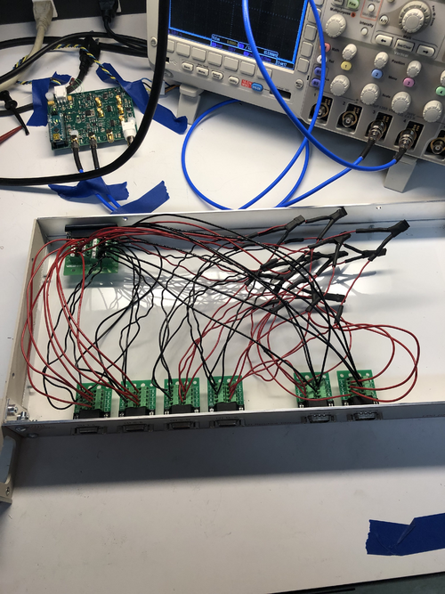
Instead of the original ratiometric method, which involved wiring the FROSTI RTDs in series, each element is individually powered by separate excitations. Each element additionally possesses its own reference resistor of 100 Ohm. Now, if an RTD experiences an electrical short, it should not affect the measurements of the others in sequence, as it had with the original design.
|
| Attachment 1: IMG_9013.jpg
|
|
|
366
|
Mon May 13 13:03:41 2024 |
Tyler | Update | FLIR | Readout Code Updates |
| [Tyler]
Some changes have been made to the FLIR readout code to help improve its functionality:
- More accurate temperature readings than before due to updates in the calculation procedure. A bug was causing one of the parameters to not update correctly; this is now fixed.
- Saved data now stored in HDF5 files rather than CSV.
- User can now enable automatic data storage by specifying a collection interval (in minutes). The choice of manually saving data is still present if desired.
Below is an image of the graphical interface. This is an old screenshot. Visually, there is no difference between the older and newer version. The differences come from the list above, which help the user more reliably measure and store data for later analysis.
|
| Attachment 1: AcquisitionImage(Jul-18-2023_15_24).jpg.png
|
.jpg.png.png)
|
|
373
|
Mon Jun 3 14:14:39 2024 |
Tyler | Update | FLIR | Initial CIT FROSTI Analysis |
| [Tyler]
Attached below are the initial results of the CIT FROSTI testing analysis.
|
| Attachment 1: CIT_FROSTI_Analysis_Group_Meeting-2.pdf
|

|
|
375
|
Mon Jun 10 14:52:38 2024 |
Tyler | Update | FLIR | CIT FROSTI Analysis Update |
| [Tyler]
Upon further inspection, one adjustment was made to the FROSTI profile analysis: changing the transmission value of the ZnSe viewport. It was initially assumed that the viewport possessed an AR coating, which would bring the transmission into the 90% range. Without the coating, it drops to roughly 70%. Assuming no coating, the estimated delivered power was calculated to be 11.7 W. This is consistent with the estimated power given from the Hartmann sensor analysis, thus it is believed that the viewport indeed had no coating.
| Quote: |
| [Tyler]
Attached below are the initial results of the CIT FROSTI testing analysis.
|
|
| Attachment 1: FROSTI_HR_Temperature_Difference-7.png
|

|
|
416
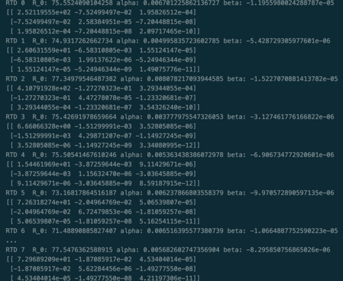
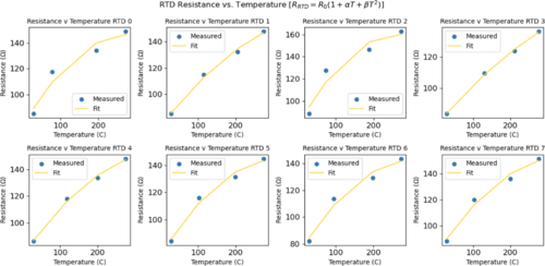
|
Mon Jul 29 13:39:16 2024 |
Tyler | Update | DAQ | RTD Parameter Calibration |
| [Tyler]
Using the data taken during the FROSTI testing at Caltech, I attempted to find a better calibration of the RTD sensors, given our past issues with inaccurate readings. The fit parameters, alpha and beta, are still all different from the initial values given to us by Fralock (alpha = .003, beta = 1.003e-6, R_0 was not given), but the true values will differ based on factors such as part geometry.
| Quote: |
| Refitted RTD calibration, neglecting quadratic term:
R_0 (ohm) Alpha (1/C)
RTD 0 79.3962 0.002031
RTD 1 78.2874 0.002530
RTD 2 80.9775 0.002381
RTD 3 74.2947 0.003684
RTD 4 80.3199 0.002157
RTD 5 78.2106 0.002297
RTD 6 76.6825 0.002438
RTD 7 82.6645 0.002458
Measurements taken can be found here. An uncertainty of 1 C was assumed for temperature.
| Quote: |
| [Jon,Tyler]
We noticed that the RTD temperature readings given on the Cymac were off, and traced the issue to miscalibration in the relationship between the resistance and temperature of each RTD (Callendar-Van Dusen eqn). Below is the table of values inferred from independent measurements of temperature and resistance to rectify this problem. This data was then fitted to better determine the coefficients present in the temperature-resistance relation:
R_0 (ohm) Alpha Beta
RTD 0 80.8674 0.001315 4.273e-6
RTD 1 79.5704 0.001887 3.7873e-6
RTD 2 81.7334 0.002014 2.1724e-6
RTD 3 74.3060 0.003677 3.6022e-8
RTD 4 81.1350 0.001761 2.3598e-6
RTD 5 77.9610 0.002423 -7.5192e-7
RTD 6 78.7980 0.001373 6.2909e-6
RTD 7 83.8616 0.001890 3.3529e-6 |
|
|
| Attachment 1: RTD_Recal_params.png
|
|
| Attachment 2: RTD_recal_plots_fin.png
|
|
|
417
|
Mon Jul 29 14:30:16 2024 |
Tyler | Update | Cleanroom | RIN Measurement Set-up |
| [Tyler]
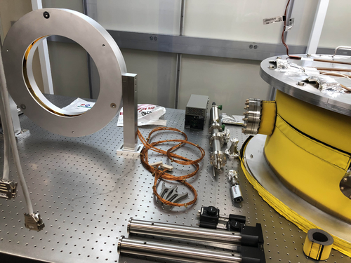
I have begun moving parts into the cleanroom for the upcoming FROSTI RIN tests that will be conducted within the next few weeks. While waiting for the rest of the equipment to arrive to perform the full-scale tests, I have additionally moved the FROSTI under the shelf above the optical table, where it will stay for the meantime. As always, please use caution when in the cleanroom. Aside from the FROSTI, the IR photodetectors that will be used for the test are delicate and costly to replace.
|
| Attachment 1: RIN_FROSTI.jpg
|
|
|
422
|
Mon Aug 12 16:24:34 2024 |
Tyler | Update | Cleanroom | RIN Measurement Update 1 |
| [Tyler]
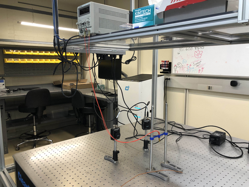
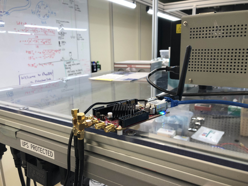
For some preliminary tests, I moved the IR photodetectors outside of the cleanroom and onto the other optical table. The basic goal was to obtain a signal from both photodetectors. To achieve this, one of the heater cartridges used for early FLIR measurements months ago was hooked up to a power supply (PS). The PS was set to supply 0.20 A with a voltage of 2.8 V; the corresponding power is thus 0.56 W. With this, I was able to measure a signal using the Red Pitaya, the device that will be used for following RIN measurements.
| Quote: |
| [Tyler]
I have begun moving parts into the cleanroom for the upcoming FROSTI RIN tests that will be conducted within the next few weeks. While waiting for the rest of the equipment to arrive to perform the full-scale tests, I have additionally moved the FROSTI under the shelf above the optical table, where it will stay for the meantime. As always, please use caution when in the cleanroom. Aside from the FROSTI, the IR photodetectors that will be used for the test are delicate and costly to replace.
|
|
| Attachment 1: Basic_setup.jpg
|
|
| Attachment 2: RP.jpg
|
|
|
434
|
Tue Sep 3 18:24:17 2024 |
Tyler | Update | CDS | Cymac Timing Chassis Issue |
| [Tyler, Jon]
The timing chassis used for the cymac has been shut off due to an unknown issue causing its supplied current to fluctuate. All real-time models will be suspended until a solution is found.
|
|
442
|
Mon Sep 16 14:59:51 2024 |
Tyler | Update | TCS | FLIR RIN Update 09/16 |
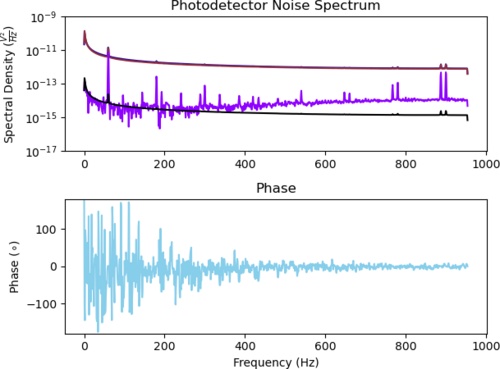
Below is the dark noise spectrum of the Red Pitaya, which was measured over the course of a weekend. Additionally, I have successfully measured a signal from the photodetectors with the FROSTI as the IR source, so it seems there shouldn't be any worry of these particular detectors not being feasible for the RIN measurement. |
| Attachment 1: adc_noise_floor_photodectors.png
|
|
|
447
|
Mon Sep 23 15:11:21 2024 |
Tyler | Update | Scripts/Programs | Effective Emissivity Analysis and RIN Update |
A quick update on the effective emissivity analysis for the CIT FROSTI testing:
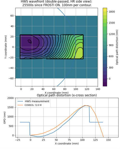
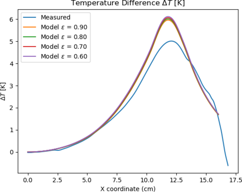
I was able to (roughly) match the OPD data to a referenced COMSOL model, with an applied power of 12.6 W (as seen below). However, when changing the emissivity of the ETM in COMSOL, the dT profiles do not seem to change much. I am not sure as to why this is the case at the moment, and will continue to look further.
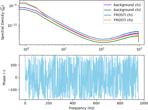
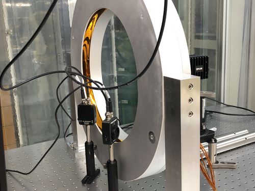
Additionally attached are the current RIN measurements of the FROSTI prototype. Shown is the PSDs of both channels, in reference to their individual backgrounds.
|
| Attachment 1: OPD_Plot.png
|
|
| Attachment 2: Temp_emiss_plot.png
|
|
| Attachment 3: rin_photodectors.png
|
|
| Attachment 4: RIN_setup.jpg
|
|
|
453
|
Wed Oct 2 12:20:43 2024 |
Tyler | Update | TCS | Updated FROSTI Analysis 10/02/2024 |
| Attached below are updates on current FROSTI prototype analysis. |
| Attachment 1: FROSTI_Analysis_Updates.pdf
|

|
|
457
|
Wed Oct 9 13:52:31 2024 |
Tyler | Update | TCS | RIN Update 10/09/2024 |
I tried adjusting the gain settings on the photodetectors to check if this would help improve the RIN spectra measurements. Overall, it doesn't look like it does, and if anything, looks worse. I assume this is so because as the gain is lowered, the amount of detectable signal from the FROSTI becomes smaller and smaller. |
| Attachment 1: RIN_plots_CH0.pdf
|

|
|
466
|
Tue Oct 29 16:37:35 2024 |
Tyler | Update | Electronics | Red Pitaya OS Update |
The Red Pitaya ecosystem has been upgraded to OS 2.00-35, with a key feature being greater freedom in adjusting the sampling frequency for signal analysis. Before, decimation factors could only be applied if they were a power of 2 (i.e 2,4,8,16,...) up to 65536. Now, the factors can be any power of two up to 16, and any whole number greater than 16 up to 65536. Further information can be found here. |
|
470
|
Wed Nov 13 14:03:32 2024 |
Tyler | Update | Electronics | RIN Update |
| [Tyler]
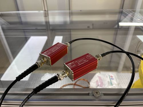
We've added two low-pass filters in hopes of reducing any potential aliasing that may be introducing additional noise into the power spectra for the RIN measurements. It still looks like the noise levels are too high. Attached below are some recent measurements taken with the FROSTI powered on and off.
|
| Attachment 1: IMG_0463.jpg
|
|
| Attachment 2: CH0_CH1_ASDs.pdf
|

|
|
477
|
Wed Nov 20 12:59:37 2024 |
Tyler | Update | Electronics | RIN Update |
| I went ahead and compared the noise spectrum of the ADC to those of the photodetectors with the FROSTI on and off. As discussed last meeting, it looks like the measurements with the Red Pitaya (RP) are limited by the ADC noise floor. Another avenue to explore in this measurement could be switching to the cymac ADCs. |
| Attachment 1: ASD_plots.pdf
|

|
|
479
|
Wed Nov 27 13:48:01 2024 |
Tyler | Update | Electronics | RIN Update |
| [Tyler]
I downgraded the Red Pitaya back to OS 2.00-18 due to runtime errors during measurement. Once I did this, the device appeared to work much better than it has the last few weeks. First, it appears we can actually see the cutoff of the added low-pass filters that were added in to the RIN setup. Second, there does appear to be a difference again between the FROSTI ON state versus the dark state (i.e. FROSTI OFF). A long measurement of the ADC noise floor in the current configuration still needs to be recorded, but it does appear that the recent highlighted issues with the Red Pitaya have been solved.
|
| Attachment 1: New_ASD_plots.pdf
|

|
|
486
|
Wed Dec 11 13:39:30 2024 |
Tyler | Update | Electronics | RIN Update 12/11/2024 |
| [Tyler]
Attached below are updated ASD plots for the FROSTI RIN measurements. The parameters set for this are the following:
- DFT Size (N): 16384
- Sampling Frequency (F_s): 7.629 kHz
- Resolution (F_s/N): 0.93
- CH0 DC Voltage w/FROSTI ON: 113.6 mV
- CH0 DC Voltage w/FROSTI OFF: -5.7 mV
- CH1 DC Voltage w/FROSTI ON: 113.0 mV
- CH1 DC Voltage w/FROSTI OFF: -5.7 mV
Each measurement was recorded over a roughly two-day period. Before each spectrum was computed, the time-series signals were AC-coupled (i.e. the DC offset was subtracted from the data). The low-pass filters are still attached for dark and light noise measurements. ADC noise is measured with two 50-ohm terminators attached to the Red Pitaya inputs rather than the IR photodetectors.
|
| Attachment 1: Updated_ASD_plots.pdf
|

|
|
492
|
Wed Dec 18 15:41:56 2024 |
Tyler | Update | TCS | FROSTI RIN |
| [Tyler]
I have begun the (hopefully) final RIN measurements at 3:30 PM today. If you need to go into the cleanroom at any time between now and Sunday (the 22nd), please do not touch the FROSTI, the Red Pitaya, the photodetectors, or any of the wiring. |