| ID |
Date |
Author |
Type |
Category |
Subject |
|
24
|
Tue Feb 7 17:44:17 2023 |
Jon | Infrastructure | Computers | Workstation 1 (ws1) set up |
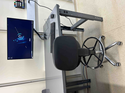
| The Linux workstation (ws1) that used to sit on the old workbench has been mounted on the new electronics bench and is now ready for use again. I upgraded the OS to Debian 11.6 and also upgraded the CDS workstation tools. |
| Attachment 1: ws1.jpg
|
|
|
26
|
Fri Feb 10 16:34:45 2023 |
Huy Tuong Cao | Infrastructure | Clean & Bake | Nitrogen gas tank ready to use |
| Cao,
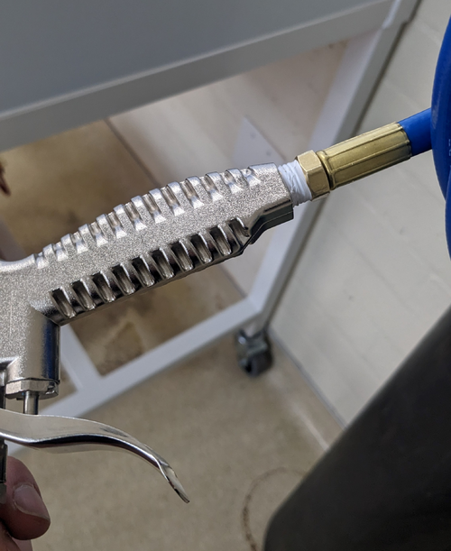
Today I fixed the final bit related to the nitrogen gas tank, which is to apply sealing tape to M-NPT connector of the hose to prevent
leakage (file: AirGunSealed.jpg)
After application of the tape, no audible leak can be heard from connection between the hose and the air gun.
The general operating procedure for the gas tank is as following:
- Turn the regulator (blue handle) anti-clockwise still it's loose
- Turn the valve on nitrogen as tank anti-clockwise, immediately the RHS meter of the regulator would jump to approx 2000 psi. This is the standard pressure for high pressure gas tank
- Turn the regulator clock-wise slowly until the pressure one the LHS meter face reads approx 60 psi. This is sufficient for drying parts with. At this point, the flow pressure still should register zero
- Press the trigger on the air gun, a high pressure air flow should come out and the flow meter should increase
- When finished, close the gas tank valve, turn the regulator anti-clockwise, then press the air gun trigger to release gas left in the hose/gun
|
| Attachment 1: AirGunSealed.jpg
|
|
|
39
|
Wed Mar 1 21:27:20 2023 |
Jon | Infrastructure | Cleanroom | Over-table shelf height raised |
Jon, Cao
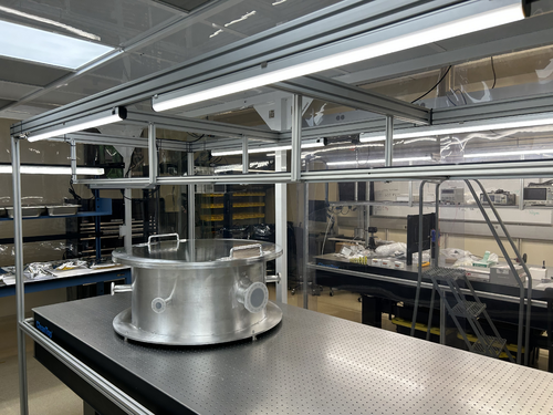
Today we raised the height of the shelf overhanging the cleanroom laser table by 8 inches. This was done to create more vertical clearance between the top-loading vacuum chamber and the bottom of the shelf. The added clearance should make both removing the chamber lid and inserting large parts easier.
The procedure required unmounting the shelf and removing all eight vertical support posts (1" x 1" x 18.5" pieces of 80/20 unistrut). The support posts were taken to the machine shop and cut, retapped, and cleaned (coarsely, with IPA wipes) prior to reinstallation. We took care to minimize the contamination introduced into the cleanroom, but some amount of particulate from disturbing the shelf was unavoidable.
This work is completed, and the cleanroom is now ready for final cleaning (HEPA vac, mopping, and wiping down of all surfaces including the softwalls). |
| Attachment 1: cleanroom-shelf.jpg
|
|
|
40
|
Wed Mar 1 21:50:46 2023 |
Jon | Infrastructure | Computers | Workstation 2 (ws2) mounted on cleanroom cart |
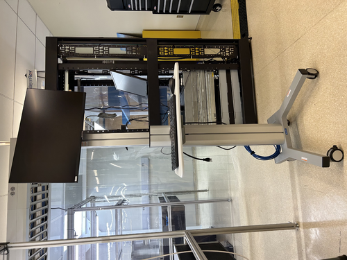
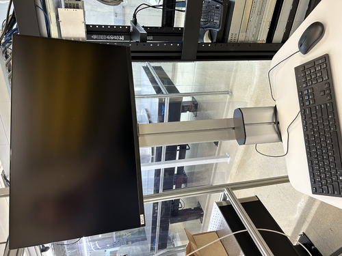
The Linux workstation (ws2) that used to sit on the blue workbench (now inside the cleanroom) has been mounted on a mobile cart, as pictured below. This is intended to be a clean cart that will be housed inside the cleanroom.
The cart is currently dirty and will need to be throughly wiped down (along with the computer monitor and peripherals) prior to being moved into the cleanroom. Once the cleaned cart has been moved inside, it should never be brought back outside the cleanroom and should never be touched with ungloved hands.
I also upgraded the OS to Debian 11.6 and upgraded the CDS workstation tools. |
| Attachment 1: ws2_cart-1.jpeg
|
|
| Attachment 2: ws2_cart-2.jpeg
|
|
|
44
|
Mon Mar 6 15:32:58 2023 |
Jon | Infrastructure | General | Cabinet installation completed |
Jon, Cao, Peter
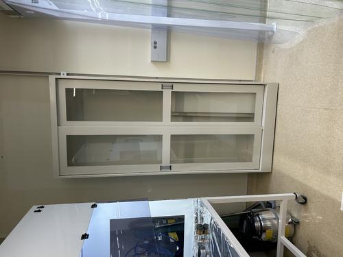
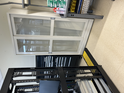
This morning Facilities delivered and installed two new cabinets with sliding glass doors.
The smaller of the two (36" W x 13" D x 84" H) has been installed in the Clean & Bake area adjacent the flow bench. The larger one (48" x 16" D x 84" H) has been installed in the back of the room next to the electronics bench. Both cabinets have been securely anchored to the wall in two places each for earthquake safety.
We also installed the sliding glass doors and leveled them. However, we have not installed any of the shelves yet because the cabinets are quite dirty from the installation. Everything needs to be wiped down with IPA wipes, and it will be easier to do that before the shelves are in place. |
| Attachment 1: IMG_0088.jpg
|
|
| Attachment 2: IMG_0089.jpg
|
|
|
53
|
Wed Mar 22 12:16:20 2023 |
Jon | Infrastructure | Cleanroom | Experimenting with HEPA fan speeds |
Jon, Cao
In effort to try to reduce the noise level inside the cleanroom, we have dialed all four HEPA fan-filter units (FFUs) down from HIGH to MEDIUM speed. These dials can only be accessed from inside the cleanroom, by bringing in the large ladder and opening adjacent ceiling tiles.
We tested three configurations, in each case with all the FFUs on either HIGH (initial state), MEDIUM, or LOW. We measured the ambient noise in each configuration.
| Fan speed |
Noise inside cleanroom (dB) |
Noise outside cleanroom (dB) |
| HIGH |
80 |
70 |
| MEDIUM |
74 |
66 |
| LOW |
71 |
66 |
Going from HIGH to MEDIUM yields the largest improvement, reducing the ambient sound intensity by 6 dB (i.e., by a factor of 4, corresponding to a ~35% reduction in perceived volume).
An additional 3 dB of noise reduction can be achieved by further reducing the fan speeds to LOW. However, even after allowing some extended settling time (few hours), we found the particle counts to be fluctuating right at the threshold zone for ISO Class 5. Thus we dialed the fan speeds back up to MEDIUM with the expectation that this will be sufficient for Class 5 performance.
The cleanroom now needs to be recertified with a fresh round of five-zone particle count measurements. |
|
56
|
Fri Mar 24 07:14:38 2023 |
Jon | Infrastructure | Computers | Workstation 2 (ws2) mounted on cleanroom cart |
| The ws2 cart has been thoroughly wiped down with IPA wipes and moved inside the cleanroom. I have reconnected it to power and Ethernet (cables bundled and ran to the server rack just outside the cleanroom). It is ready for use.
| Quote: |
The Linux workstation (ws2) that used to sit on the blue workbench (now inside the cleanroom) has been mounted on a mobile cart, as pictured below. This is intended to be a clean cart that will be housed inside the cleanroom.
The cart is currently dirty and will need to be throughly wiped down (along with the computer monitor and peripherals) prior to being moved into the cleanroom. Once the cleaned cart has been moved inside, it should never be brought back outside the cleanroom and should never be touched with ungloved hands.
I also upgraded the OS to Debian 11.6 and upgraded the CDS workstation tools. |
|
|
67
|
Tue Apr 11 13:15:40 2023 |
Cao | Infrastructure | Clean & Bake | Nitrogen gas tank replaced |
| The nitrogen gas tank has been replaced with a new unit. The new tank is ultra pure nitrogen (>99.9% nitrogen).
The new tank has been placed and secured to the rack where the old one is; cap is removed and regulator is reinstalled onto the new tank. |
|
94
|
Tue May 9 15:49:20 2023 |
Jon | Infrastructure | VAC | Permanent cable routing |
Today I brought in a fresh supply of zip ties (we now have 1500 in the tool chest) and used them to permanentize the cable routing for the gauges, pumps, and RGA.
I also brought and installed a 3-foot 15A extension cable for powering the scroll pump. Installing the cable required shutting down the pumps, which I did and then reverted via the following procedure:
- Close the 4.5" gate valve, 2.75" gate valve, and the bypass line angle valve.
- Shut down the turbo pump.
- Shut down the scroll pump.
- Unplug the scroll pump and install the extension cable.
- Power on the scroll pump.
- Power on the turbo pump.
- Open all three valves.
Incidentally, before I started, I noticed that the pressure in the main volume had reached 7E-7 torr, which is lower than the pressures seen last week. The system quickly returned to this pressure after I restarted the pumps. |
|
95
|
Tue May 9 20:55:12 2023 |
Jon | Infrastructure | VAC | Calibrated Ar leak rate |
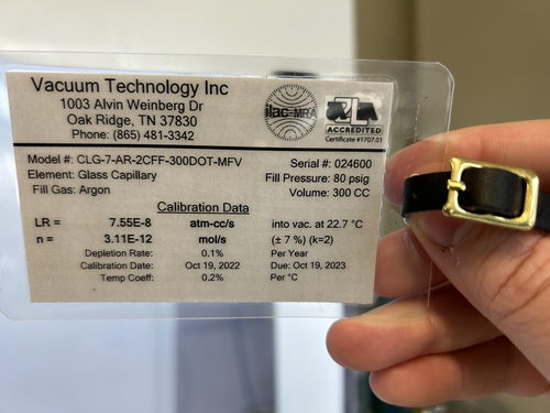
For future reference, the calibrated Argon source has a leak rate of 7.55E-8 atm cc/s, or equivalently 5.74E-8 torr L/s. This can be used to calibrate RGA scans to units of physical leakage (outgassing) rate. |
| Attachment 1: VTI-Calibrated-Ar-Leak.jpeg
|
|
|
98
|
Sun May 14 15:50:48 2023 |
Cao | Infrastructure | Computers | High resolution display of logrus machine |
| [Cao]
The display resolution of the logrus has been 1064x768 and has been the only option, which is not great. While remote access to logrus using rdesktop allows rendering a virtual display of user's chosen resolution, it is not fast when using graphic-intensive program. NoMachine allows user to take over and control the machine remotely and thus appears as the same machine. However, NoMachine cannot render a virtual display like rdesktop. This has been limiting the resolution of using logrus via NoMachine.
On Friday, I found that even though we had NVIDIA Quadro P600 graphic card installed, we were not actually using it. The monitor has been connecting to the the integrated VGA display connector. This uses Microsoft Basic Display Adapter which limits the the resolution. Today I got a HDMI to Mini-display cable to connector the monitor to the Nvidia graphic card. Then in Display settings, go to Graphic settings, then enable Hardware-accelerated GPU scheduling. After restarting the machine, the machine recognised the Display 2using the Nvidia Quadro P600. In multiple displays field, selected "Show only on 2" and remove the VGA connection to the monitor. Logrus is now set at Nvidia Qadro P600 native display resolution of 1920x1080. This is now also the display resolution in NoMachine.
|
|
122
|
Tue Jun 13 21:08:46 2023 |
Pamella | Infrastructure | VAC | Heater system - Installation |
[Pamella, Cao and Jon]
Heating system installation
- Today we started installing the equipments for the heating system.
- First: Started installing the heating cable on the top lid and covered it with aluminum tape.
- Second: Started installing the insulation cover on top of the chamber lid.
- Third:Started installing the heating cable from under the vacuum chamber and covered with aluminum tape.
- Forth: Started installing the insulation cover under the vacuum chamber
- Note: The under part of the chamber vacuum was very difficult to cover, so we spent a little time on it and we couldn't finish the whole installation today. So tomorrow we should be able to keep doing the installation.
|
| Attachment 1: IMG_7563.jpeg
|
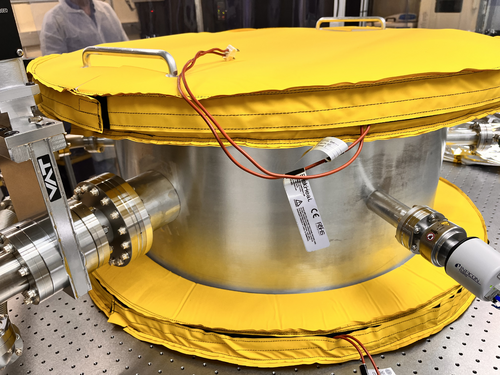
|
| Attachment 2: IMG_7561.jpeg
|
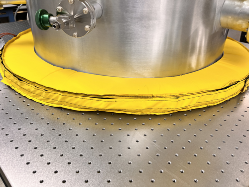
|
|
129
|
Tue Jun 20 22:14:24 2023 |
Pamella, Cao | Infrastructure | VAC | Short term testing of vacuum heater controller units |
| [Pamella, Cao]
Fuse replacement
- Replace blown 10A fuse in ucontroller outside cleanroom
- Replace 10 A fuse in main power connection slot of the controller unit inside cleanroom
- Pamella wiped down unit outside cleanroom.
- Controller units turned on and temperature setpoint set to be 80 deg C
- Temperature settle in approx. 15 minutes(as recorded by the RTD). No problems with fuses observed
- Recording of pressure gauges (in Torr) :
- Before turning heater on :
- Gauge 1(main chamber): 3.73E-7
- Gauge 2(RGA line): 3.65E-7
- Gauge 3(Pump line): 3.8E-4
- After 15 minutes :
- Gauge 1(main chamber): 7.07E-7
- Gauge 2(RGA line): 6.12E-7
- Gauge 3(Pump line): 3.8E-4
- Reduce setpoint temperature to 60 deg C due to Pinrani gauge (Gauge 3) temperature limit
- Upon returned to lab to reduce temperature (35 minutes after turned on):
- Gauge 1(main chamber): 1.22E-6
- Gauge 2(RGA line): 9.98E-7
- Gauge 3(Pump line): 3.8E-4
- Once temperature has settled to 60 C (approx 20 mins after changing setpoint), pressure readout showed:
- Gauge 1(main chamber): 1.37E-6
- Gauge 2(RGA line): 1.10E-6
- Gauge 3(Pump line): 3.8E-4
- Heater left on for the whole afternoon, pressure readout upon returning to lab at 5:30 pm:
- Gauge 1(main chamber): 3.43E-6
- Gauge 2(RGA line): 2.61E-6
- Gauge 3(Pump line): 3.8E-4
|
|
130
|
Wed Jun 21 20:25:05 2023 |
Cao | Infrastructure | VAC | Vacuum chamber bake attempt 1 |
TL;DR:
We are not yet able to bake the chamber at 150 deg C due to some current limit, most likely caused power supply switching off. Also, smoke was observed at some insulation points, mainly in the small arm sections, This is likely because the insulation does not fit well and the velcro came into direct contact with heat tape. Some Velcro (made from Nylon/ Polyester) has lower melting temperature point (in 90-120 deg C range)
Full version:
20 June 23:
- Turn off heater (short term testing) Close valves to RGA line and main volume. Pressure (Torr) readout:
- Gauge 1 (main volume): 3.43E-6
- Gauge 2 (RGA line): 2.61E-6
- Gauge 2 (pump line): 3.8E-4
- Turn off turbo pump, let vacuum line vent
- Connect high temperature control unit to main power, power up, set setpoints:
- Temperature setpoint: 150 deg C
- High temperature setpoint (to switch off) : 175 deg C
- Hysteresis: 10 dec C
- change setpoint of PID control unit to 150 dec C, with high alarm set at 165 deg C
- Connect power output of high temperature control units to PID temperature control units, ensuring both are off
- Turn off scroll pump
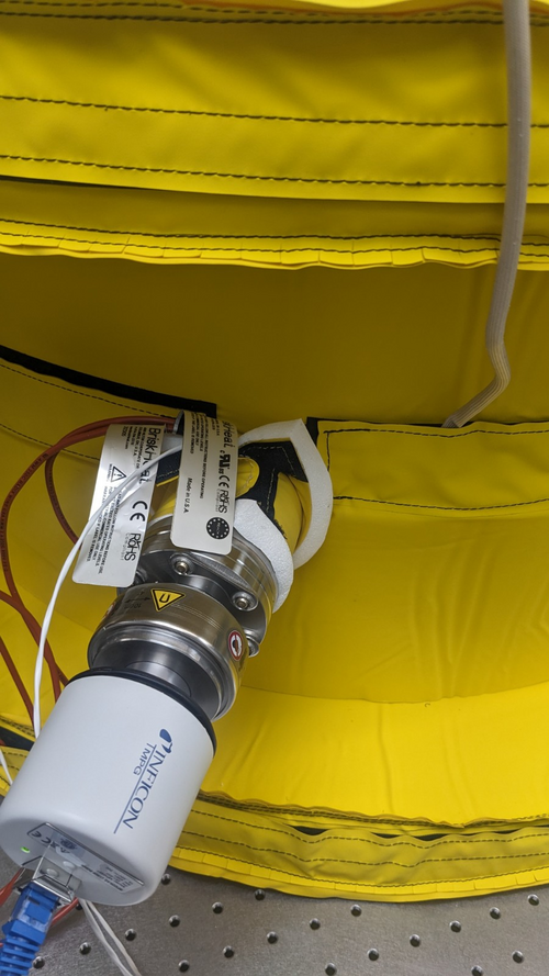
- Replace Pirani gauge in front of turbo pump with blanks (see image)
- Pump the vacuum line back down
- Open up valves and wait until pressure of full system drop back down to 1E-6
- Install the high temperature controller thermocouples onto the chamber (see images):
- One thermocouple is installed on the other side of the cross before the turbo pump
- One thermocouple is installed on the main volume next to the PID controller RTD
- Attempt to remove electronic box and magnetic shield of full range gauges:
- Electronic box is easily removed with an Allen key
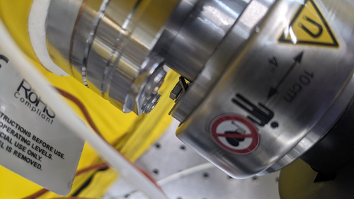
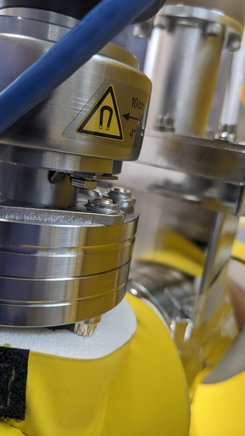
- Magnetic shield cannot be removed since the gap between the vacuum flange and the gauge bolt is too short for a spanner to go in. This is mainly due to the bolt washers are in the way (see images)
- To remove the magnetic shield, the main volume has to be vented and the gauges need to be readjusted.
- Attempt to power heaters (but only heat to 80 deg C):
- Leaving the gauges intact, the high temperature controller + PID controller are turned on to test heating the chamber
- At this point, both of the high temperature controllers are connected to the same power strip (Vacuum chamber end of the table)
- After heating up to 65-70 deg C range, the powers turned off on both controllers + the lights on one end of the table
- Upon inspection, the power strip has turned itself off, I don't know what the model of the power strip but we should check its current limit
- For a quick test, I connect one of the two heater controlling system to the power board on the work desk while leaving the other running off the same power strip: The heaters appeared to be function ok and able to reach 80 deg C, at which point I turned it off and left for the day
21 June 23:
The goals of today was to remove the electronic boxes and magnetic shields on full range gauges to enable high temperature bakeout
- Upon returning to the lab, the gauges readout of vacuum pressures were:
- Gauge 1 (main volume): 3.31E-7
- Gauge 2 (RGA line): 3.40E-7
- Venting the both main volume and RGA line
- Remove the two full range gauges from their flanges
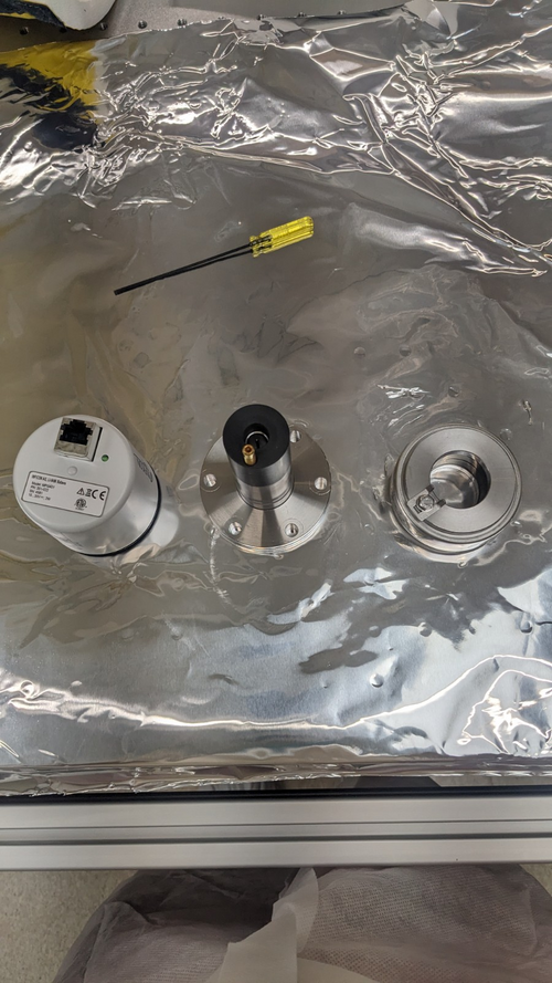
- Electronic boxes and magnetic shields were removed according to the gauge manuals (see images)
-
- Mount the gauges (with only its probing volume) back onto their respective flanges, ensuring that the flange washers do not block access to the magnetic shield screws
- Only remount magnetic shield + electronic box for one gauge (gauge 2: RGA line) for monitoring chamber pressure
- Turn on scroll pump and let the chamber pump down
- Rearrange heater controller connections while waiting for pumping down:
- Controllers for bottom + pump & RGA line heaters remain the same: connected to power strip on vacuum end of the table
- Controllers for lid + upper chamber main volume: connected to power strip on clean&bake end of the table
- Once the pressure readout by gauge 2 reached 3 Torr, the turbo pump was turned on and left to run for 45 minutes
- Upon returning to the lab, pressure on gauge 2 read 5E-6 Torr and was still decreasing
- Disconnect the ethernet cable to gauge 2, remove its electronic box and magnetic shield
- Turn on heater controller units and let them drive the heaters to get up 150 deg C
- At 95 degree range, I could see smoke at some locations, mainly the RGA and pump lines where the insulation do not fit properly and the velcros are likely to be overheated
- Upon reaching 90 degree range (measured by sensors), the powers turned off on both sides of table (including heaters, lights and scroll pump)
- Turn off both heaters controllers and unplug them from power strip. Attempt to switch the power strip back on but nothing happened
- It is now not the power strips problem and must be further down the line from outside the tent, most likely the power supply that these strips connected to: What is the power supply model + current limit?
- The heater controllers left unplugged, I temporarily plugged scroll pump to the desk power strip so it can still run
|
| Attachment 1: Pirani_gauge_blankReplacement.jpg
|
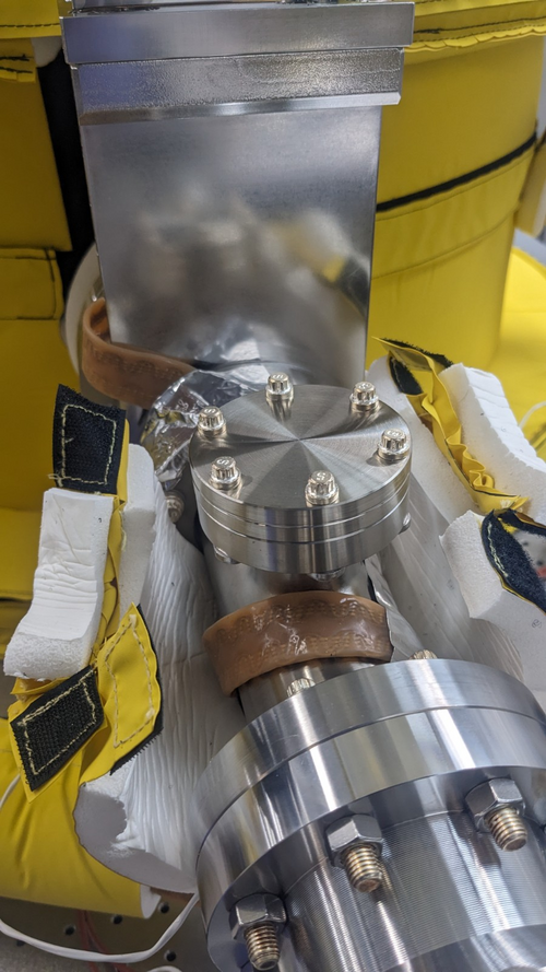
|
| Attachment 2: ThermoCouple1.jpg
|
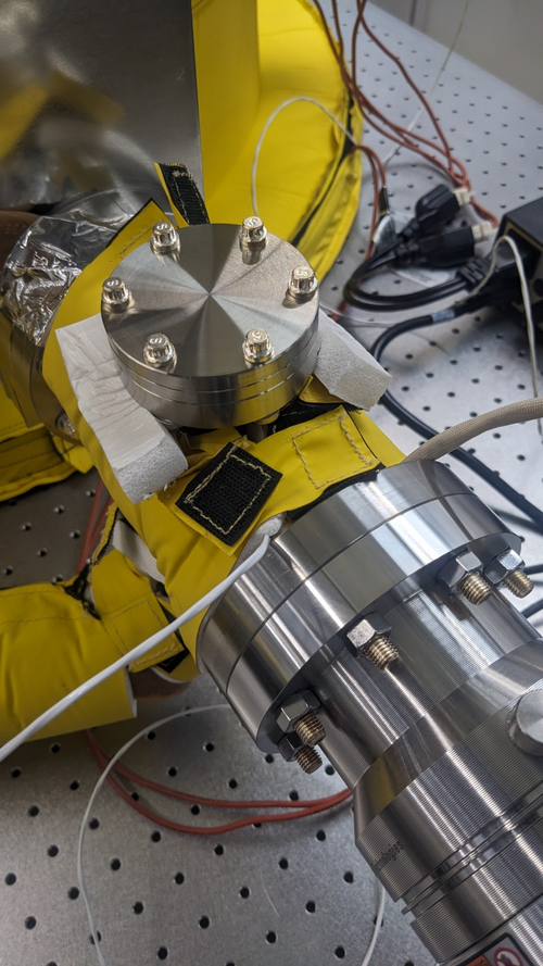
|
| Attachment 3: ThermoCouple2.jpg
|
|
| Attachment 4: Gauge1_magneticShield_screw.jpg
|
|
| Attachment 5: Gauge2_magneticShield_screw.jpg
|
|
| Attachment 6: Fullrange_gauges_components.jpg
|
|
|
136
|
Tue Jun 27 21:47:56 2023 |
Jon | Infrastructure | VAC | Vacuum chamber bake attempt 1 |
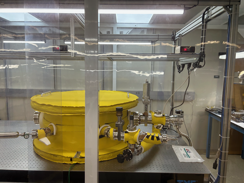
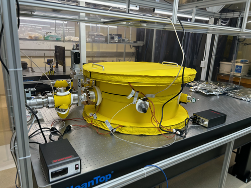
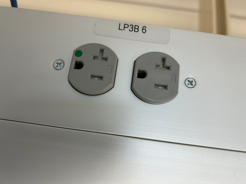
The electrical overload problem encountered in ELOG 130 has been resolved. The two heater controllers, which draw up to 14.1 A each, overloaded the UPS and tripped one of its circuit breakers, shutting off power to both power strips mounted above the optical table.
I reset the circuit breaker and rerouted the two heater power cables instead to two separate 20 A outlets in the overhead cable tray outside the cleanroom (both on the LP3B 6 circuit). The two high-limit temperature controllers are now permanently positioned, as shown in the photos. For now, the PID controllers have been left sitting at the table level. I am ordering extension cords that will enable us to move those up to the overhead shelf, as well. I ran the heaters in their new configuration for several minutes without issue. Thus we should be able to now proceed with baking the chamber.
For future clarity, I added labels to power strips around the lab indicating which ones are powered by the UPS. To avoid overloading the UPS, only sensitive electronics or devices that could be damaged by a sudden loss of power should be connected to these. |
| Attachment 1: IMG_0256.png
|
|
| Attachment 2: IMG_0257.png
|
|
| Attachment 3: IMG_0254.png
|
|
|
137
|
Wed Jun 28 15:58:56 2023 |
Shane, Cao | Infrastructure | VAC | Power trip problem remains, source of smoke is insulation |
| [Shane, Cao]
With the new change in wiring configuration described in elog 136, we tried to power up the heaters for baking the vacuum chamber again.
Given that we were worried about the turbo pump overheats, we set the setpoints of of bother high temperature controller and PID controller to be 120 deg C before turning the heaters on
1. Evidence of smoke originating from CoolSkin insulation
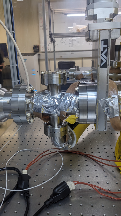
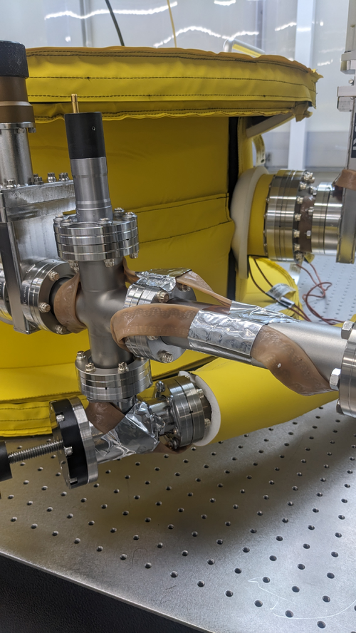
We then removed most of the CoolSkin insulation on the Pump and RGA lines ( apart from the one around the flexible bypass line connecting the two ) (see image Pumpline_afterRemoveInsul and RGAline_afterRemoeInsul) .
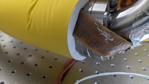
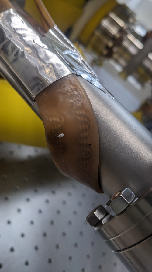
Upon removal of the insulation, we noticed that the insulating foam melted onto the heating tape (see image MeltedInsulation1 and MeltedInsulation2). This is the first indication that the smoke had most likely coming from the insulating foam itself
Once we started baking, upon reaching 80 degree range. We observed no smoke at the location that we removed the insulation. However, We observed smoked coming from underneath the insulation around the flexible pipe, and not from the velcro areas.
What could be causing this, given that the maximum operating temperature of the insulation is 200 deg C? Most likely, the heating tape is much hotter than we think it is. But given that the temperature sensor readout is much lower than 200 deg C, it's likely that this is due to poor thermal contact and it takes a while for sensor to reach a thermal equilibrium with the heating tape. Here, I suggest we should implement the following:
- We should look into usingsome form of thermal tape (if possible to secure the temperature sensors)
- Unfortunately or controller does not allow programming process, we will have to implement manual temperature stepping, emulating ramping process over the first hour, until slowly reach 120 deg C
- OR Tune the PID controller coeffs, especially P and I for longer rise time and settling time
2. The heaters still trip our power
Upon reaching 80 deg C,our main power trip. Unfortunately I don't know how to reset this. Do we need to contact facility on this? Reading elog 136, I noticed that both controllers are connected to the same circuit LP3B 6, which is the same circuit the some of the fan-filters and LED light panels of the cleanroom connected to. From the elog, the circuit has a 20 A limit . An max operation, the 2 heater controllers draw 30 Amps, approx 7 Amps for the fan-filters, and another 1.5 A for LED panel. The combination of these equipment must have overload the circuit and tripped it . Currently half the fans + lights are off in the cleanroom are off due to power trip. Here, I would make a suggestion that each heater controller should be connected to a separate circuit . Currently we LP3B 7 (same side next to LB3B 6) and LB3B 4 (opposite side of the rail) having no equipemts connected to them, but will require cable extensions. |
| Attachment 1: Pumpline_afterRemoveInsul.jpg
|
|
| Attachment 2: RGAline_afterRemoeInsul.jpg
|
|
| Attachment 3: MeltedInsulation1.jpg
|
|
| Attachment 4: MeltedInsulation1.jpg
|

|
| Attachment 5: MeltedInsulation2.jpg
|
|
|
138
|
Thu Jun 29 18:27:26 2023 |
Jon, Cao | Infrastructure | VAC | Vacuum bake attempt 3: success! |
| [Jon, Cao]
Summary : We resolved problems with heaters tripping power and were able to proceed with chamber baking
1. Circuit connection adjustment
After yesterday elog 137, today we resolved most of these issues. After Jon contacted Facilities, the LP3B 6 circuit was reset and the cleanroom filter & light panels resumed to work as normal.
Regarding the connection of the heaters. we made the following adjustments:
- High-temperature controller powering lid + upper volume heater: connect to LP3B 8 circuit (clean room sides, 2 outlets)
- High-temperature controller powering bottom + lower volume heater : connect to LP3B 4 circuit (workstation side, 2 outlets)
2. Replacement of vacuum nipple insulation
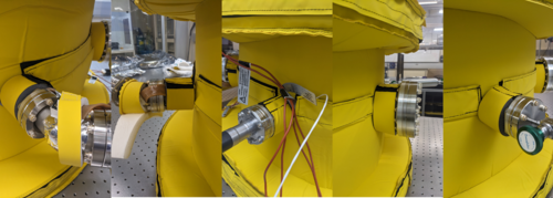
We had also received new insulation pieces from Worbo today to replace the existing insulation with the new ones (see images). These cover the 2 4" tubes (for 6" flanges ) and the 4 1.5" tubes (for 2.75" flanges). The new insulations fit perfectly on these tubes.
I also placed all insulation taken off from the last elog back onto the chamber ( these are insulations for the pumps and RGA lines).
3. Baking
We started ramping up chamber temperature at 1:41 pm over the course of two hours:
- Starting set point: 40 deg C
- Step increase: 10 deg C up to 80 deg C, 5 deg C from 80 deg to 120 deg C
- At each step, the temperature readouts show approx. 2.1 deg C overshooting, wait to settle back to approx 1.5 deg C overshoot before increase the set point again
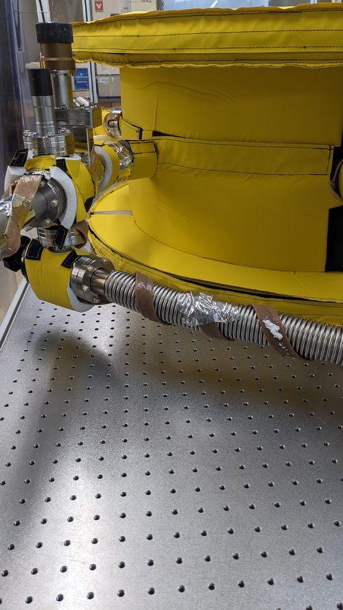
We noticed some smoke emanating from flexible bypass line insulation but none from other locations that were previously smoking . We think this is because the high winding density around the bypass line for such a small volume. Adjustment for next bake: Change the location of PID controller RTD to the bypass line . For now, we remove the insulation around bypass to prevent insulation overheating and encourage convection cooling (see image)
The temperature of the chamber reached as stable 120 deg C without any power issues at 3:45 pm. I waited another 15 minutes to verify its stability and the official baking duration started at 4:00 pm Jun 29 2023. Since we are baking at 120 deg C instead of the standard 150 deg C for Aluminium, the duration for the bake will be over three days until Monday morning, upon which we will slowly ramp down the the temperature.
|
| Attachment 1: NewInsulation.png
|
|
| Attachment 2: BypassLineInsulation.jpg
|
|
|
141
|
Mon Jul 3 14:32:24 2023 |
Cao | Infrastructure | VAC | Cooling down vacuum chamber |
| [Cao]
After leaving the the chamber to bake at 120 deg C from Thursday 3:41 pm. Today I started to cool the chamber down to room temperature at 11:30 am (total bake duration: 91 hours 49 minutes). Ideally, this process should be ramped down slowly, approx. 6 degree per hour. However we had no ramping function with out controller. The only method to tune this cool/ heat rate is to tune the PID parameters, which are:
- Pb : Proportional band, this quantity is inversely proportional to the P-gain
- ti : Integral time. Increasing integral time makes the output response slower to error, thus the opposite effect of increasing integration gain
- td : Differential time
Since the differential term doesn't contribute to rise time significantly, we neglect it for now and first change Pb and ti . The factory default settings :
- Pb : 50
- ti : 100 s
- td : 25 s
Initially Ichanged Pb from 50 to 200 (max) and ti to 999 s (max) but there is a large offset error. Currently, Pb and ti are sitting on the following settings:
- Pb : 200
- ti : 800 s
At this setting it takes 25-30 mins to drop 6 degrees, which is not as slow as we want but we will have to tune our PID more carefully.
At the first stage, I dropped the temperature to 60 deg C. After 3 hours, we dropped the setpoint to 25 degrees and let the vacuum chamber to cool to room temperature. |
|
142
|
Mon Jul 3 16:26:21 2023 |
Cao | Infrastructure | DAQ | Access and control Red Pitaya remotely and run it on local machine |
| [Cao]
To access and control the Red Pitaya using Python locally on a machine within the local network, one should follow these steps:
-
Start the SCPI server. This is achieved by first log onto the Red Piatay page
rp-xxxxxx.local/
- Go to Development >> SCPI server and turn the server on. (Note : The server is currently running)
- Communication with Red Piataya is done through PyVista, install PyVista with:
sudo pip3 install pyvisa pyvisa-py
This has been installed on Chimay. Ensure that you have pip3 install, if not, you can install it using:
sudo apt-install python3 pip
- To start talking to the RedPitaya, ensure you have the scipt
redpitaya_scpi.py in your local folder. This is the standard class that you will import to your code to establish connection with the Red Pitaya. This code can be found in directory ~/RedPiatya or this link
|
|
145
|
Wed Jul 5 15:46:47 2023 |
Aiden, Cao | Infrastructure | VAC | Vacuum Chamber Baking Update |
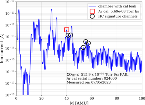
Cao and Aiden put the RGA back on to the chamber and measured the outgassing rate after the chamber has cooled down from its first bake. The figure attached shows the RGA measurements with the Argon leak open.
Also put the Full Range Gauge #2 [RGA line] back onto the system to measure the pressure and got a reading of 2.78 E-7 Torr. We believe it is actually lower as the chamber temp is still at 28 degC rather than the 24 it was previously measured at. The gauge also may have needed more time to equilibrate.
|
| Attachment 1: bake1_230705.png
|
|
|
198
|
Wed Aug 9 11:32:56 2023 |
Jon | Infrastructure | General | New power cables |
I delivered new NEMA 5-15 (120V / 15 A) power cables to the lab for the following items:
- WS2 (cleanroom) cart - 10ft cable
- Electronics workbench overhead LED - 10ft cable
- Both PI heater controller sets - (2) 6ft cables
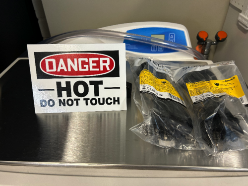
I installed the new cables on the WS2 cart and the workbench myself, and left the two 6ft cables (as pictured below) for Aiden to install on the PID controllers after the current bake is finished. |
| Attachment 1: IMG_0299.jpg
|
|
|
294
|
Sun Dec 17 21:04:15 2023 |
Jon | Infrastructure | Clean & Bake | Clean and bake lab migrated to 1129 |
[Jon, Tyler, Aiden, Luke]
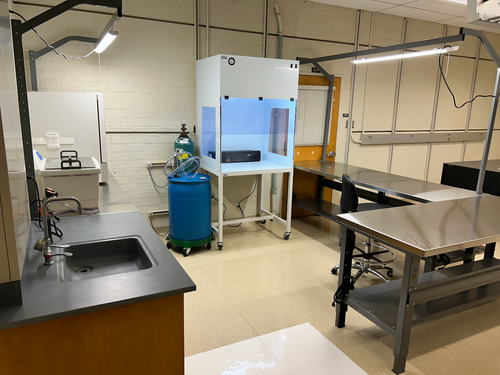
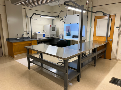
On Friday we completed assembly of the new stainless steel-topped benches in 1129. We then moved the clean and bake equipment from 1119 to its new larger space in 1129. This included the HEPA flow bench, ultrasonic washer, deionized water drum, nitrogen tanks, and forced-convection oven. The oven was re-anchored to the wall with earthquake restraints in its new location.
The power cords still need to be permanently routed, but the new clean and bake lab is otherwise ready for use. |
| Attachment 1: IMG_0781.png
|
|
| Attachment 2: IMG_0782.png
|
|
|
297
|
Wed Dec 20 10:33:34 2023 |
Jon | Infrastructure | Clean & Bake | Clean and bake lab migrated to 1129 |
Update: I have completed permanent routing of the electrical cables. I also ran the ultrasonic washer's drain line to the sink drain (the current hose does reach). The new clean and bake lab is now fully operational.
| Quote: |
|
[Jon, Tyler, Aiden, Luke]
On Friday we completed assembly of the new stainless steel-topped benches in 1129. We then moved the clean and bake equipment from 1119 to its new larger space in 1129. This included the HEPA flow bench, ultrasonic washer, deionized water drum, nitrogen tanks, and forced-convection oven. The oven was re-anchored to the wall with earthquake restraints in its new location.
The power cords still need to be permanently routed, but the new clean and bake lab is otherwise ready for use.
|
|
|
303
|
Mon Jan 15 22:29:34 2024 |
Jon | Infrastructure | General | Cabinet installation & lab clean-up completed |
[Jon, Tyler, Aiden, Shane, Pooyan, Michael, Cynthia, Luke]
On Wednesday, we completed long list of work towards making the new lab (1129) fully operational and enabling the next phase of FROSTI testing.
Cabinet Installation
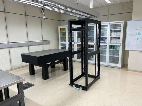
Three new VWR cabinets with sliding glass doors were installed in 1129. Each unit measures 48" (W) x 22" (D) x 84" (H) and sits along the back wall (see attachment 1). The 350-lb. cabinets were laid in place by Facilities on Monday and permanentized on Wednesday. Work included:
- Earthquake anchoring to the masonry wall
- Sliding glass doors leveled
- Shelving installed
- Wiping down of interior and exterior surfaces with IPA wipes
Server Rack Installation
A new Tripp Lite 42U open-frame rack was laid in place in 1129 and anchored to the floor (see attachment 1). This rack will house all of our general-purpose and simulation computers, which will be relocated from the 1119 rack at a later time.
Lab Clean-Up
Following installation of the new cabinets and rack, we proceeded to organize and clean both labs. Work included:
- Moved parts and equipment into permanent storage in 1129 cabinets
- Wiped down surfaces in 1119 and 1129 with polypropylene IPA wipes
- HEPA-vacuumed floors of 1119 and 1129
- Mopped floor in 1119 with Liquinox solution
- Installed new sticky mats in 1119 and 1129
- Regular cleanroom cleaning and particle counts (see 302)
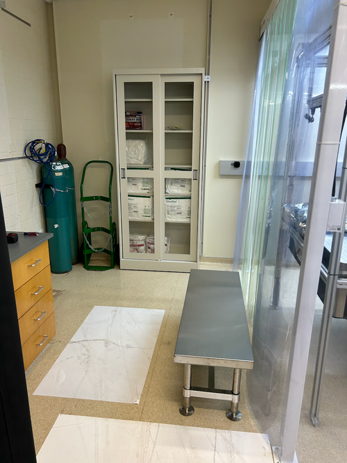
- Positioned new stainless steel gowning bench outside the cleanroom (see attachment 2)
At this point, the only piece of lab equipment still to be delivered is a HEPA garment cabinet for reusing our (semi-disposable) bunny suits. It is schedule to arrive in mid-February and will sit outside the cleanroom in 1119, in the former location of the HEPA flow bench. |
| Attachment 1: 1129.png
|
|
| Attachment 2: 1119.png
|
|
|
330
|
Tue Feb 20 08:01:30 2024 |
Jon | Infrastructure | General | Power and network equipment installed in 1129 rack |
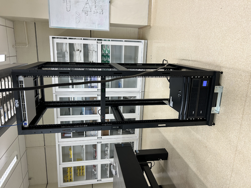
| [Jon, Tyler, Pooyan, Luis, Luke, Peter]
On Thursday we installed the power conditioning/distribution equipment and networking equipment in the new 1129 rack. The hardware is identical to the setup in the 1119 rack and includes:
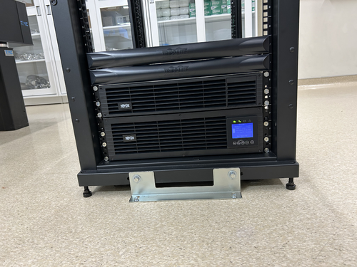
- Tripp Lite SU5KRT3UTF - 208V, 5kVA on-line UPS with 120V transformer
- CyberPower PDU20M2F12R - metered power distribution unit, (14) NEMA 5-20R
- Ubiquiti USW-Pro-48 - 48 port 10Gbps network switch
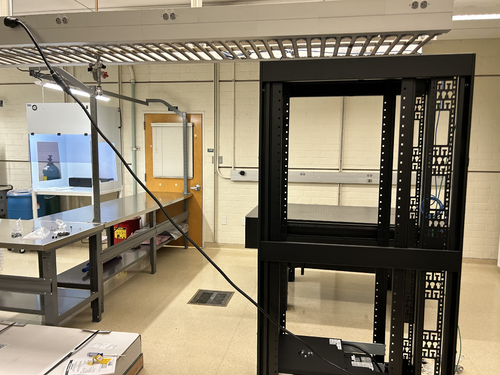
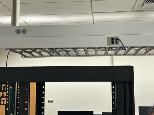
The UPS is connected to a 208V NEMA 6-30R outlet in the overhead cable tray, which is on the building's "standby" (backup power) circuit. An 8-ft L6-30 extension cord has been ordered to permanently run the power cable through the cable tray.
The network switch will be connected to a Cat6 cable that was recently run by ITS from the 1119 rack, allowing the lab's LAN to be extended into 1129. This Ethernet link remains to be tested.
| Quote: |
Server Rack Installation
A new Tripp Lite 42U open-frame rack was laid in place in 1129 and anchored to the floor (see attachment 1). This rack will house all of our general-purpose and simulation computers, which will be relocated from the 1119 rack at a later time.
|
|
| Attachment 1: IMG_0924.jpeg
|
|
| Attachment 2: IMG_0925.jpeg
|
|
| Attachment 3: IMG_0921.jpeg
|
|
| Attachment 4: IMG_0922.jpeg
|
|
|
339
|
Sat Feb 24 08:53:38 2024 |
Jon | Infrastructure | Computers | Matlab upgraded to 2023b on Chimay |
| I upgraded Matlab on chimay to the latest stable release, 2023b. From some quick tests, it appears to be in working order. Let me know of any issues. |
|
377
|
Mon Jun 17 11:47:46 2024 |
Liu | Infrastructure | General | Temporary cooling units for the labs |
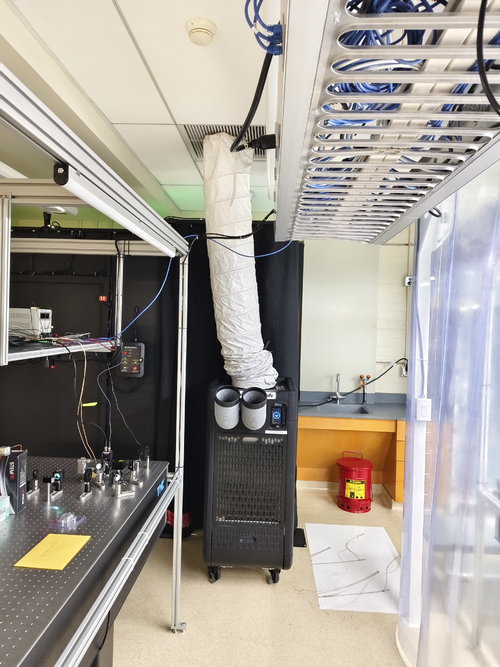
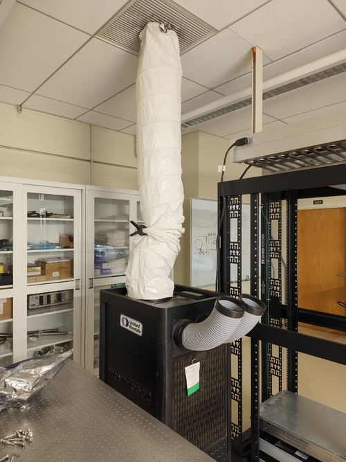
| Below are the temporary cooling units installed last week in labs 1119 and 1129. They are the temp. replacement for the building AC system, which will be shut down during the Physics roof replacement. |
| Attachment 1: 1119.jpg
|
|
| Attachment 2: 1129.jpg
|
|
|
379
|
Thu Jun 20 18:01:11 2024 |
Jon | Infrastructure | Computers | New workstation ws3 in 1129 |
| I have repurposed a spare Intel NUC to serve as the first of two planned workstations in 1129. Today I set it up with a fresh installation of Debian 12.5, assigned it the static IP address 192.168.1.15, and installed the LIGO CDS workstation packages. It is assigned the host name ws3.
Temporarily, the mouse is borrowed from ws1 in 1119. We need to order another mouse as well as a 25-ft Ethernet cable for connecting the workstation to the 1129 switch, via the ceiling. |
|
382
|
Mon Jun 24 21:38:25 2024 |
Pooyan | Infrastructure | Computers | Computer server changes in 1119 and 1129 |
[Jon, Pooyan, Tyler]
A few computer machine changes have been made.
- Logrus moved from 1119 to 1129. It is up and running with the same IP address as before.
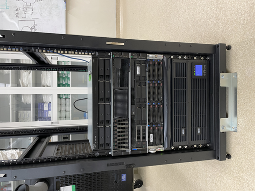
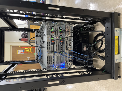
- A new Windows machine (host name: spica, IP:192.168.1.14) is installed in the 1119 server rack. It is connected to the RGA scanner with the serial port and is specifically used for that purpose.
- Update: The machine was off on 6/25, although it was left on 6/24. We think that it might have been because of Windows' default setting to suspend/hibernate the machine after idleness. To resolve this, I used "powercfg /change" command to set all the following parameters equal to zero. The machine is still running on 6/26.
    monitor-timeout-ac
    monitor-timeout-dc
    disk-timeout-ac
    disk-timeout-dc
    standby-timeout-ac
    standby-timeout-dc
    hibernate-timeout-ac
    hibernate-timeout-dc
-
A new Debian machine (hostname: megatron, IP:192.168.1.16) is installed in the 1129 server rack. This machine is intended to be used for FEA/simulation work. A new 2TB WD Green SSD is used as its main disk drive.
At the moment, “controls” is the only user, and there are no apps/libraries installed on the machine.
- Update: Jon installed LIGO cds-workstation tools and MiniConda on 6/26.
- Update: Pooyan and Liu set the following conda environments:
- Env named “finesse” with Python 3.12.3 and Finesse version 3.0a24 installed. Finesse was installed via the source code. The subdirectory “/home/controls/packages” is used to store the package sourcecodes.
- Env named “fenicsx” with the same version of Python and Finesse as the previous env, with the latest version of FEniCSx (0.8) and the test-mass-thermal-state installed.
|
| Attachment 1: IMG_6889.jpg
|
|
| Attachment 2: IMG_6890.jpg
|
|
|
385
|
Wed Jun 26 15:33:41 2024 |
Jon | Infrastructure | Computers | New workstation ws3 in 1129 |
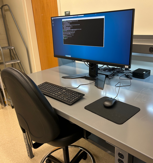
Set-up of the first CDS workstation for 1129, ws3, is complete and the machine is ready for use. The login credentials are the same as the other lab machines.
All that now remains is to install a permanent cable tray for running the new Ethernet cables between the electronics rack and bench (they are currently dangling from the suspended lights).
| Quote: |
| I have repurposed a spare Intel NUC to serve as the first of two planned workstations in 1129. Today I set it up with a fresh installation of Debian 12.5, assigned it the static IP address 192.168.1.15, and installed the LIGO CDS workstation packages. It is assigned the host name ws3.
Temporarily, the mouse is borrowed from ws1 in 1119. We need to order another mouse as well as a 25-ft Ethernet cable for connecting the workstation to the 1129 switch, via the ceiling. |
|
| Attachment 1: IMG_1368.jpg
|
|
|
402
|
Thu Jul 11 21:01:37 2024 |
Jon | Infrastructure | General | Cable tray installed in 1129 |
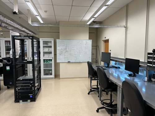
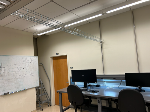
| Today I installed a 10' cable tray in 1129, for permanently routing Ethernet lines to the workstations. It is securely bolted to C-channels in the side wall and in the center cable tray. |
| Attachment 1: IMG_1395.png
|
|
| Attachment 2: IMG_1396.png
|
|
|
412
|
Fri Jul 26 17:25:42 2024 |
Jon | Infrastructure | Computers | New workstation ws4 installed in 1129 |
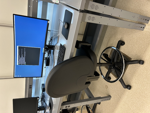
Today I installed the second desktop workstation in 1129. The new machine is an Intel NUC13ANHi5, with a 12-Core Intel i5-1340P CPU, 32GB DDR4 RAM, and a 1TB SSD.
I loaded it with a fresh installation of Debian 12 and installed the LIGO CDS workstation (control room) tools. It is assigned the hostname ws4 and and the static IP address 192.168.1.19 on the local lab network. Like the other CDS workstations, there is just one user account accessible with the usual credentials.
The machine is fully set up and ready for use. |
| Attachment 1: ws4.jpg
|
|
|
418
|
Tue Jul 30 07:42:47 2024 |
Jon | Infrastructure | General | Cable tray installed in 1119 |
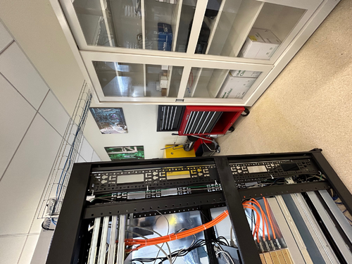
| Yesterday I installed another 5' cable tray in 1119, for permanently routing Ethernet lines to the L-bench. It is securely bolted to the top of the electronics rack, on one end, and to the top of the glass-door storage cabinet, on the other. This eliminates the need for the cable ramp which previously sat behind the rack. |
| Attachment 1: cable_tray_1119.jpg
|
|
|
437
|
Mon Sep 9 14:27:36 2024 |
Pooyan | Infrastructure | Computers | Chimay backup attempt |
One ongoing work is to make all lab machines automatically backed-up on Scribe on a daily basis. The updates should be boatable and stored for some time (potentially a few weeks) on Scribe. Making whole disk images has already been tried for some of the machines with no problems. (e.g., Cymac and WorkStations)
The same thing can not be done with Chimay though, as it currently has one huge RAID-controlled volume that stores all the information (OS, home directories, and NDS-downloaded data). Creating daily full disk images of such a system is not practical.
Here is the plan we came up with to overcome this issue:
- Create one full disk image of Chimay and store it on Scribe (it was already done)
- Move the nds-downloaded raw data temporarily to Scribe and remove it from Chimay
- Make another full disk image of Chimay
- Burn this image to a single disk and boot chimay with it
-
Restore the rest of Chimay disks and move the NDS data back
On the weekend (Sat and Sun 9/7-8) I tried to execute these steps. There wasn't enough free space left on Scribe to move all the NDS data to it, so I stored part of this data temporarily on WS4. Then I also checked storage-consuming directories and, in one case, removed some non-important stored files. As there was no free space left on Scribe to execute step no. 3, I initiated storing the image on WS3. Unfortunately, a couple of different trials of the image-creation process failed as there was not enough free space on WS3 to accommodate Chiamy image as well. I was not able to reduce the image size such that it can be stored on WS3.
These are the options left for us to get this work done.
- Distribute the NDS files between different machines to make enough free space on Scribe for the image and then follow the previous plan
- Shrink the Chimay drive size, create the image and then follow the previous plan
- Temporarily transfer some services to Megatrone (Network gateway, Wiki, elog) and recreate chimay and its services from scratch
|
|
578
|
Thu May 15 12:03:41 2025 |
Xuesi Ma | Infrastructure | Electronics | Notice |
All Sorensen power supplies are turned off. The Cymac system is down (All Chassis are down)
If you need more information or if you need to turn them back on please contact Xuesi Ma. |
|
579
|
Mon May 19 10:59:14 2025 |
Xuesi Ma | Infrastructure | | |
Status Update
Previous Status:
All Sorensen power supplies were turned off. The Cymac system was down (all chassis were offline).
If you need more information or assistance in turning them back on, please contact Xuesi Ma.
Update: The systems are now back online.
Note: The Sorensen power supplies’ voltage can now be controlled via channel VEXC8 of the DAC.
If scripting is required, the ezca Python package is highly recommended for interfacing and control.
|
|
580
|
Wed May 21 14:40:38 2025 |
Xuesi Ma | Infrastructure | Cleanroom | Cleanroom Temperature |
|
Date and Time: Around 2:20 PM on May 21, 2025
Location and Temperature:
- Back of the room, around the working station: 85.5 °F
- Front of the room, around the doorway: 82.3 °F
|