| ID |
Date |
Author |
Type |
Category |
Subject |
|
356
|
Wed Mar 27 00:03:57 2024 |
Pooyan | Update | Computers | Chimay relocation to Physics 1129 |
[Jon, Pooyan]
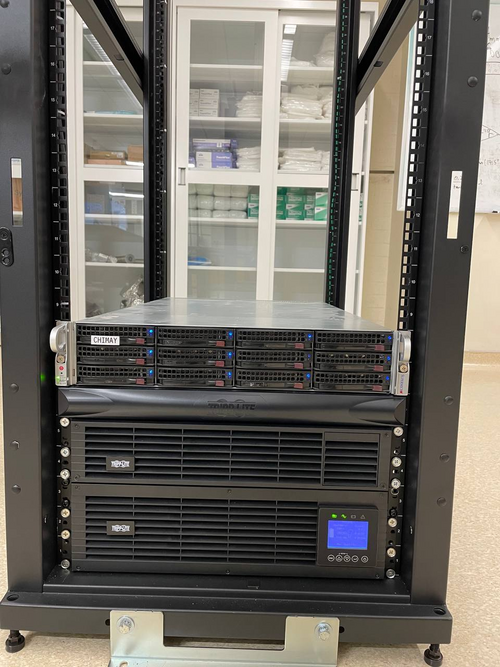
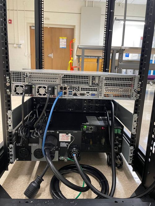
Moved Chimay from the server rack in Physics 1119 to a new rack in Physics 1129. It is connected to the switch in that rack and has the same ip address as before.
All services are up and running.
It appears that JupyterHub creates some processes whenever a user connects to an instance of it, but in some cases does not stop those processes after the user is not using that instance. This results in having lots of running idle processes, each using a small bit of the resources. Those processes are killed now as a result of rebooting. It might be a good idea to manually restart JupyterHub (or the whole machine) every few months to avoid this. |
| Attachment 1: Chima_front.jpg
|
|
| Attachment 2: Chimay_back.jpg
|
|
|
355
|
Tue Mar 26 13:51:56 2024 |
Tyler | Update | DAQ | RTD Parameter Calibration |
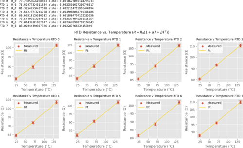
Another re-fit, but this time the quadratic coefficient (beta) is set to 1.003e-6:
R_0 (ohm) Alpha (1/C)
RTD 0 79.7386 0.001863
RTD 1 78.6248 0.002359
RTD 2 81.3254 0.002211
RTD 3 74.6127 0.003509
RTD 4 80.6652 0.001988
RTD 5 78.5450 0.002127
RTD 6 77.0144 0.002268
RTD 7 83.0204 0.002288
| Quote: |
| Refitted RTD calibration, neglecting quadratic term:
R_0 (ohm) Alpha (1/C)
RTD 0 79.3962 0.002031
RTD 1 78.2874 0.002530
RTD 2 80.9775 0.002381
RTD 3 74.2947 0.003684
RTD 4 80.3199 0.002157
RTD 5 78.2106 0.002297
RTD 6 76.6825 0.002438
RTD 7 82.6645 0.002458
Measurements taken can be found here. An uncertainty of 1 C was assumed for temperature.
| Quote: |
| [Jon,Tyler]
We noticed that the RTD temperature readings given on the Cymac were off, and traced the issue to miscalibration in the relationship between the resistance and temperature of each RTD (Callendar-Van Dusen eqn). Below is the table of values inferred from independent measurements of temperature and resistance to rectify this problem. This data was then fitted to better determine the coefficients present in the temperature-resistance relation:
R_0 (ohm) Alpha Beta
RTD 0 80.8674 0.001315 4.273e-6
RTD 1 79.5704 0.001887 3.7873e-6
RTD 2 81.7334 0.002014 2.1724e-6
RTD 3 74.3060 0.003677 3.6022e-8
RTD 4 81.1350 0.001761 2.3598e-6
RTD 5 77.9610 0.002423 -7.5192e-7
RTD 6 78.7980 0.001373 6.2909e-6
RTD 7 83.8616 0.001890 3.3529e-6 |
|
|
| Attachment 1: Screenshot_2024-03-26_at_1.23.27_PM.png
|
|
|
354
|
Mon Mar 25 10:55:33 2024 |
Tyler | Update | DAQ | RTD Parameter Calibration |
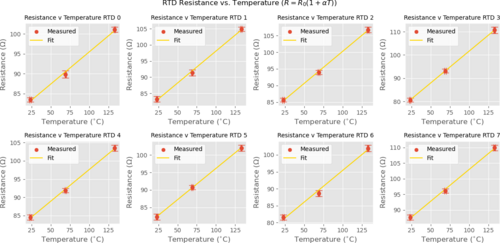
| Refitted RTD calibration, neglecting quadratic term:
R_0 (ohm) Alpha (1/C)
RTD 0 79.3962 0.002031
RTD 1 78.2874 0.002530
RTD 2 80.9775 0.002381
RTD 3 74.2947 0.003684
RTD 4 80.3199 0.002157
RTD 5 78.2106 0.002297
RTD 6 76.6825 0.002438
RTD 7 82.6645 0.002458
Measurements taken can be found here. An uncertainty of 1 C was assumed for temperature.
| Quote: |
| [Jon,Tyler]
We noticed that the RTD temperature readings given on the Cymac were off, and traced the issue to miscalibration in the relationship between the resistance and temperature of each RTD (Callendar-Van Dusen eqn). Below is the table of values inferred from independent measurements of temperature and resistance to rectify this problem. This data was then fitted to better determine the coefficients present in the temperature-resistance relation:
R_0 (ohm) Alpha Beta
RTD 0 80.8674 0.001315 4.273e-6
RTD 1 79.5704 0.001887 3.7873e-6
RTD 2 81.7334 0.002014 2.1724e-6
RTD 3 74.3060 0.003677 3.6022e-8
RTD 4 81.1350 0.001761 2.3598e-6
RTD 5 77.9610 0.002423 -7.5192e-7
RTD 6 78.7980 0.001373 6.2909e-6
RTD 7 83.8616 0.001890 3.3529e-6 |
|
| Attachment 1: RTD_Calib_nobeta.png
|
|
|
353
|
Sun Mar 24 11:50:37 2024 |
Aiden | Update | Clean & Bake | Cal Tech FROSTI Parts |
| Bagged the FROSTI legs and feet after the conclusion of the clean and bake. They are double bagged and sitting in the flow bench. |
|
352
|
Sun Mar 24 11:49:27 2024 |
Aiden | Update | General | FROSTI RGA Scan |
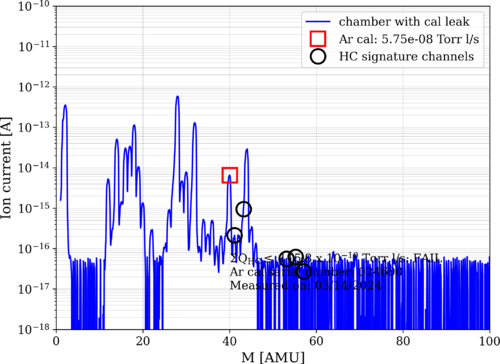
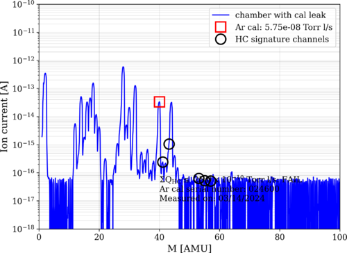
| Took RGA data 1 day after the conclusion of Bake 13. Bake 13 ended on Saturday March 23, the RGA data shown was taken on Sunday March 24. The scan shows that the FROSTI is very clean with no outgassing. The HC levels are at 25 e-10. The pressure in the chamber was also a 1.64 e-8 Torr. |
| Attachment 1: bake13_240324_FROSTI_ArC.png
|
|
| Attachment 2: bake13_240324_FROSTI_ArO.png
|
|
|
351
|
Thu Mar 21 16:56:42 2024 |
Tyler | Update | DAQ | RTD Parameter Calibration |
| [Jon,Tyler]
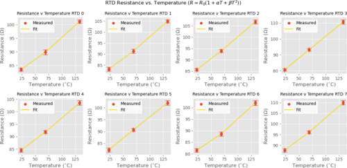
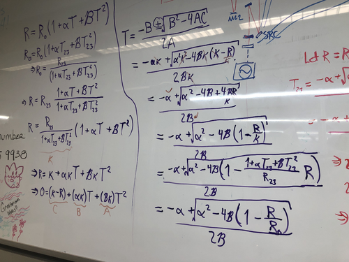
We noticed that the RTD temperature readings given on the Cymac were off, and traced the issue to miscalibration in the relationship between the resistance and temperature of each RTD (Callendar-Van Dusen eqn). Below is the table of values inferred from independent measurements of temperature and resistance to rectify this problem. This data was then fitted to better determine the coefficients present in the temperature-resistance relation:
R_0 (ohm) Alpha Beta
RTD 0 80.8674 0.001315 4.273e-6
RTD 1 79.5704 0.001887 3.7873e-6
RTD 2 81.7334 0.002014 2.1724e-6
RTD 3 74.3060 0.003677 3.6022e-8
RTD 4 81.1350 0.001761 2.3598e-6
RTD 5 77.9610 0.002423 -7.5192e-7
RTD 6 78.7980 0.001373 6.2909e-6
RTD 7 83.8616 0.001890 3.3529e-6 |
| Attachment 1: RTD_Calib-2.png
|
|
| Attachment 2: IMG_8569.jpg
|
|
|
350
|
Tue Mar 19 15:22:27 2024 |
Aiden | Update | Clean & Bake | FROSTI Legs Clean and Bake |
| [Aiden, Luke]
Cleaned and baked the Cal Tech FROSTI legs and showed Luke the procedure on how to clean parts. |
|
349
|
Tue Mar 19 10:55:30 2024 |
Tyler | Update | FLIR | In-Air Optical Test |
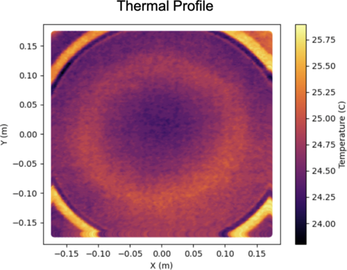
| Below is an image I took using the FLIR just before leaving for the LVK meeting. The profile is roughly what we would expect (annular). Any distortions seen are likely from the screen not being completely parallel to the plane of the FroSTI (i.e. the screen slightly bends in various locations). Next step: In-vacuum test at CIT. |
| Attachment 1: FroSTI_Thermal_Profile.png
|
|
|
348
|
Fri Mar 15 16:58:55 2024 |
Aiden | Update | VAC | Vacuum Chamber Frosti Testing |
| [Luke, Luis, Aiden]
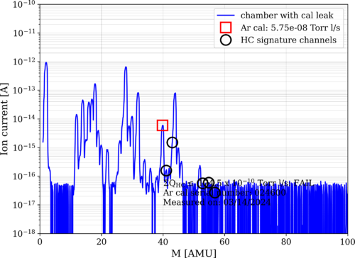
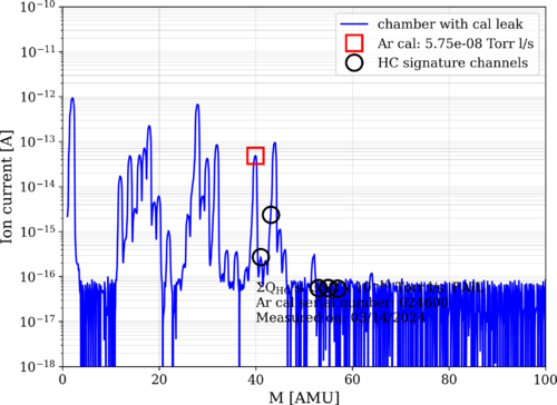
On Thursday, March 14 - Took preliminary RGA scans of the empty chamber to compare later on. Vented the chamber and placed the FROSTI into the chamber. Plugged in the DB-25 connectors into the feed through port and checked the connection to make sure there were no shorts before closing the chamber and starting the pumps again.
On Friday, March 15 - The pressure in the chamber has come down to 7 e-6 torr. It seems to be coming down much slower despite the little time the chamber was left open for. This may be due to the FROSTI being out on the table for so long and a bake may be needed to bring the pressure down to near UHV. |
| Attachment 1: bake12_240314_Empty_ArC.png
|
|
| Attachment 2: bake12_240314_Empty_ArO.png
|
|
|
347
|
Wed Mar 6 09:57:52 2024 |
Tyler | Update | TCS | FROSTI Wiring |
Upon finishing the FROSTI assembly last week, we ran into some electrical issues. An electrical short was found between two of the d-sub pins (2 and 8). It appears that the pins were somehow coming into contact with the aluminum surrounding them. This was causing the power supply to trip. The issue was seemingly fixed by adjusting the positioning of the cabling leading out of the reflector. When handling the device in the future, please make sure to keep the wiring as undisturbed as possible. The setup is rather fragile, and moving the cabling around could potentially reintroduce a short like this. |
|
346
|
Thu Feb 29 17:16:48 2024 |
Shane | Update | CDS | MEDM screen for FROSTI T/P readouts |
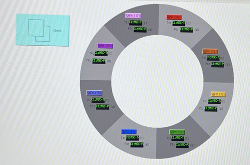
| Here's the latest draft of the MEDM screen for the FROSTI temp and power readouts, now with a button linking to the c1msc file display. Size/color/label are all changeable, if adjustment is needed. Checked in execute mode as well, and it's working correctly. Also noticed that the MEDM file name has been changed to FROSTI.adl, which I'm noting here for future reference. Still in medm_sandbox directory. |
| Attachment 1: IMG_6259.jpeg
|
|
|
345
|
Wed Feb 28 17:49:18 2024 |
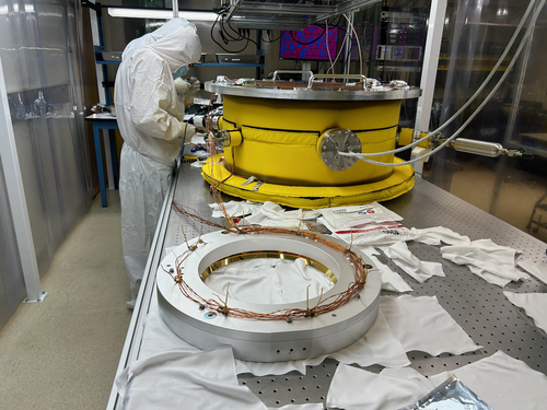
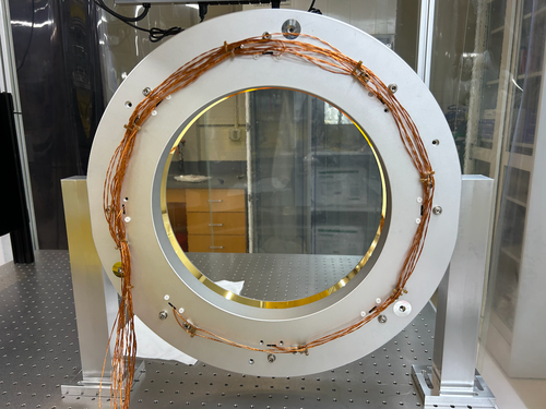
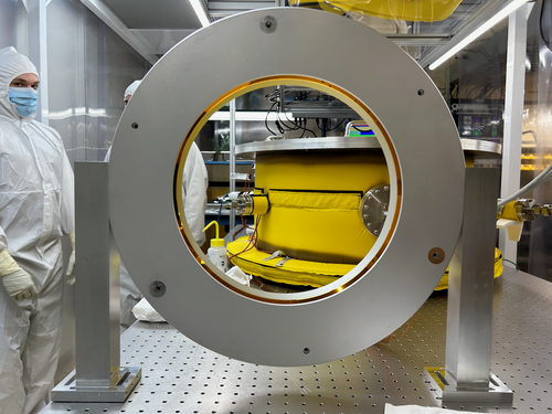
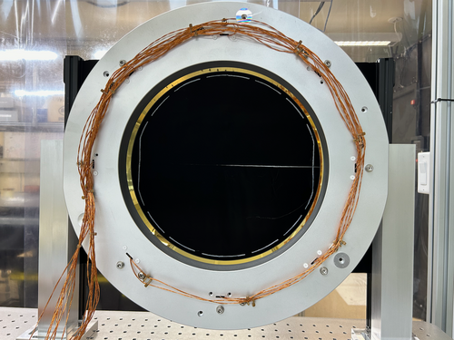
Tyler | Update | TCS | FROSTI Assembly - Days 2-3 |
| [Aiden, Jon, Luis, Luke, Michael, Tyler]
FROSTI assembly was completed today. The RTD and power wires were terminated at the DB-25 connectors and the legs were put on. It is currently placed in front of the stand-in test mass (~5 cm away). The FLIR has also been moved back to it's nominal position. As of now, it appears there are some shorts within the power cabling. This will be a focus of tomorrow's work.
| Quote: |
| [Jon, Tyler, Luis, Luke, Mohak, Cynthia, Michael, Aiden]
FROSTI assembly began today. After a final set of RGA scans were taken, the vacuum chamber was vented and the reflectors were removed. The chamber was then resealed and pumped down again.
Today we completed the installation of the Macor hardware and heater elements between the two reflector halves. Tomorrow we will route, bundle, and terminate the power and sensor cables. |
|
| Attachment 1: IMG_0947.png
|
|
| Attachment 2: IMG_0956.png
|
|
| Attachment 3: IMG_0957.png
|
|
| Attachment 4: IMG_0959.png
|
|
|
344
|
Wed Feb 28 12:02:08 2024 |
Tyler | Update | General | Resistors for Heater Elements Update |
| Power Res (Ohm) RTD Res (Ohm)
Heater 1= 72.8; 80.6
Heater 2= 69.5; 80.8
Heater 3= 70; 83.2
Heater 4= 70.6; 78.7
Heater 5= 69.9; 80.6
Heater 6= 71.1; 78.2
Heater 7= 68.5; 76.8
Heater 8= 70.1; 82.8
| Quote: |
| Power Res (Ohm) RTD Res (Ohm)
Heater 1= 73.6; 81.8
Heater 2= 70.4; 82.1
Heater 3= 71; 84.5
Heater 4= 71.5; 80
Heater 5= 70.5; 81.7
Heater 6= 72; 79.4
Heater 7= 69.2; 78.2
Heater 8= 71.1; 84.2 |
|
|
343
|
Tue Feb 27 09:06:29 2024 |
Cynthia | Update | Interferometer Simulations | cavity scan with higher order input laser |
| I performed a few cavity scan with the inputing laser with a different mode (not pure 00). For each laser I included a graph for just plotting the order with highest power (for example 1st order laser input the first plot only scanned for 1st order in that cavity), and I have also included a graph scanning for order 1-10. |
| Attachment 1: ligoPre_2_27.pdf
|

|
|
342
|
Tue Feb 27 03:26:28 2024 |
Michael | Update | Interferometer Simulations | Reverse aLIGO Layout Created in Gtrace |
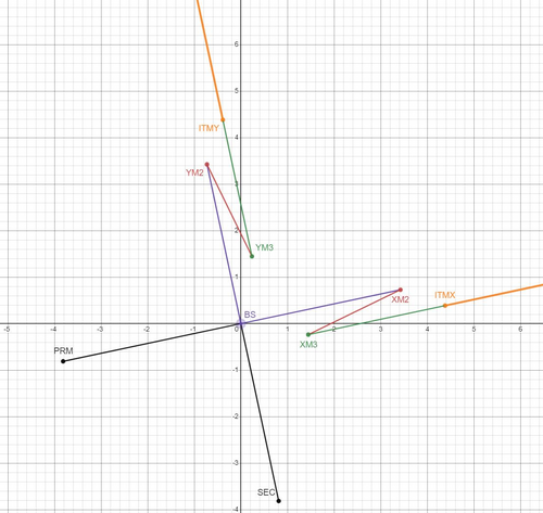
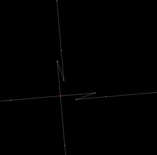
| I've created the simulation for reverse aLIGO layout in gtrace. Attached are the desmos model and the output dxf file. From here Pooyan and I plan to create a brief report of our progress to the CE optical design group. |
| Attachment 1: reverse_aligo_desmos.JPG
|
|
| Attachment 2: reverse_aligo_dxf.JPG
|
|
|
341
|
Mon Feb 26 21:23:27 2024 |
Jon | Update | TCS | FROSTI Assembly - Day 1 |
| [Jon, Tyler, Luis, Luke, Mohak, Cynthia, Michael, Aiden]
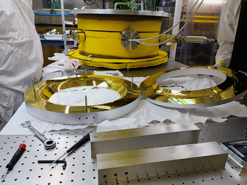
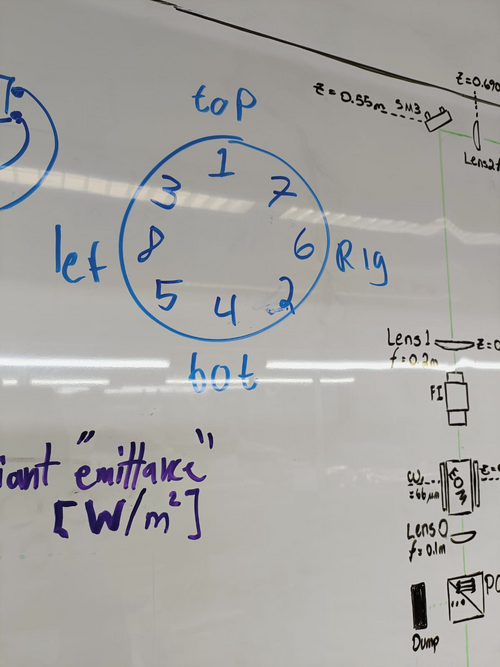
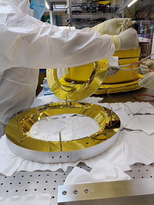
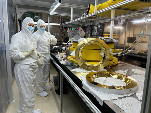
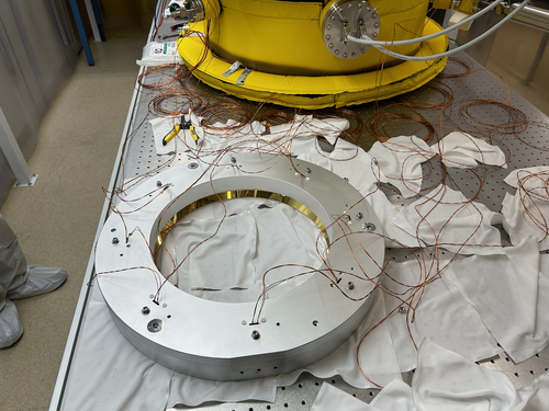
FROSTI assembly began today. After a final set of RGA scans were taken, the vacuum chamber was vented and the reflectors were removed. The chamber was then resealed and pumped down again.
Today we completed the installation of the Macor hardware and heater elements between the two reflector halves. Tomorrow we will route, bundle, and terminate the power and sensor cables. |
| Attachment 1: IMG-20240226-WA0008.jpg
|
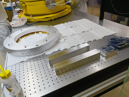
|
| Attachment 2: IMG-20240226-WA0006.jpg
|
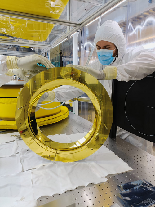
|
| Attachment 3: IMG-20240226-WA0011.jpg
|
|
| Attachment 4: IMG-20240226-WA0010.jpg
|
|
| Attachment 5: IMG-20240226-WA0012.jpg
|
|
| Attachment 6: IMG_0944.png
|
|
| Attachment 7: IMG_0946.png
|
|
|
340
|
Mon Feb 26 15:15:39 2024 |
Aiden | Update | General | Vacuum Chamber Baking Update |
| Started Bake 12 on Wednesday Feb. 21 and turned the bake off on Saturday Feb. 24. This was a normal low temp bake with the PID controllers set to 110 degC. |
|
339
|
Sat Feb 24 08:53:38 2024 |
Jon | Infrastructure | Computers | Matlab upgraded to 2023b on Chimay |
| I upgraded Matlab on chimay to the latest stable release, 2023b. From some quick tests, it appears to be in working order. Let me know of any issues. |
|
338
|
Fri Feb 23 18:03:27 2024 |
Tyler | Update | FLIR | Optical Test Setup in Cleanroom |
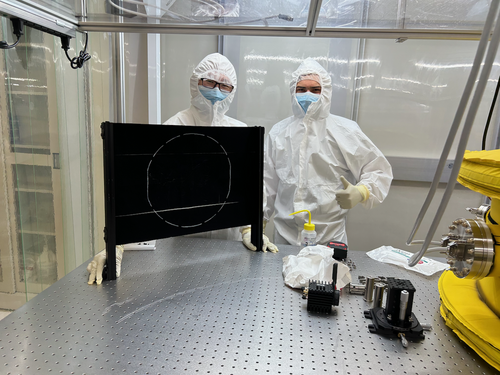
| [Tyler, Xuesi]
The FLIR and test mass stand-in have been transferred into the cleanroom. A software test will be run as soon as we get an ethernet cable long enough to reach into the cleanroom where the camera is set up. Once this is finished, the FLIR will be moved aside for construction of the FROSTI! When completed, the camera will be placed back into position for in-air optical testing.
|
| Attachment 1: IMG_0941.png
|
|
|
337
|
Fri Feb 23 15:01:48 2024 |
Shane | Update | CDS | Latest draft of MEDM screen for FROSTI readouts |
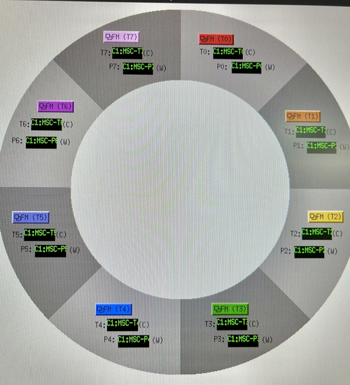
| Here's the latest draft of the MEDM screen for the FrOSTI temp and power readouts. Also, debugged the text readout boxes so they're now correctly reading out the live temperature and power values. |
| Attachment 1: IMG_6128.jpg
|

|
| Attachment 2: 23.jpg
|
|
|
335
|
Thu Feb 22 21:48:16 2024 |
Jon | Update | VAC | Vacuum vent for RGA testing of reflector |
[Jon, Tyler, Luke, Aiden]
Summary
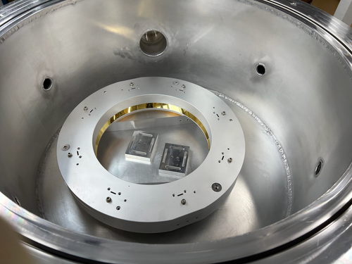
Following Wednesday's cleanroom cleaning [333], we proceeded to vent the vacuum chamber, remove the heater elements and their mount structure, and install the FROSTI reflectors. The reflectors are the final components to undergo RGA testing before the FROSTI prototype can be assembled. After installing the reflectors, we pumped the chamber back down and initiated a 48-hour 125 C bake.
Vacuum Vent
At ~1:00 pm, we shut off power to all eight of the FROSTI heater elements. Prior to shutoff, all were operating in vacuum at roughly 300 C. We then waited approximately 30 minutes for the elements' temperatures to fall below 50 C.
At this point, we isolated the RGA volume from the main volume by closing both gate valves, leaving the RGA volume to continue to be pumped through the bypass line. We then backfilled the main volume via the needle valve connected to one of the 2.75" ports. Once the pressures had equalized, we removed the chamber lid via our usual procedure (requiring only a small amount of flathead-screwdriver prying) and extracted the heater element assembly.
Reflector Assembly
We then removed the FROSTI reflectors from their protective packaging (for the very first time) on the cleanroom tabletop. We tested the fit of the Macor and stainless steel hardware in the reflectors' tapped holes. The Macor standoffs and bolts appear to fit perfectly. However, the 1/4-20 tapped holes for joining the two reflector halves are too shallow by ~1/4". As a temporary fix, we used some on-hand stainless steel washers (which had already been cleaned and baked) to securely fasten the two halves together. In the final assembly we will replace these with slightly shorter 1/4-20 vented bolts.
Pumpdown and Bake
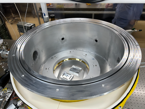
The two fastened reflector halves were placed inside the chamber, sitting on top of the two mounting legs (see attached photos). We then reinstalled the lid. In order to rough the main volume, we isolated the RGA volume from the pumpline (by closing the bypass line valve), shut down the pumps, and then backfilled the pumpline via the manual vent valve on the turbo pump.
Once the pressures had equalized, we opened the 6" gate valve separating the pumpline from the main volume and powered on the roughing pump. Once the main volume pressure fell below 0.5 Torr, we powered on the turbo pump as well. The main volume pressure reached 5e-6 Torr within ~30 minutes, consistent with previous experience, and was continuing to slowly fall.
Lastly, we initiated a 125 C bake-out of the entire system following our usual procedure. We plan to run this bake for 48 hours (i.e., through the end of the day Friday). |
| Attachment 1: IMG_0938.png
|
|
| Attachment 2: IMG_0939.png
|
|
|
334
|
Wed Feb 21 23:15:07 2024 |
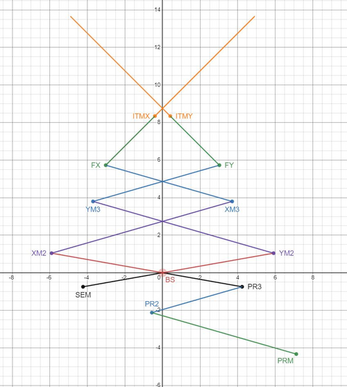
Michael | Update | Interferometer Simulations | Long Shoelaces 1 Layout Created in Gtrace and Fixed Ghosting in Beamsplitter |
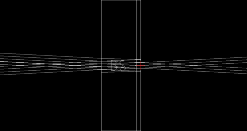
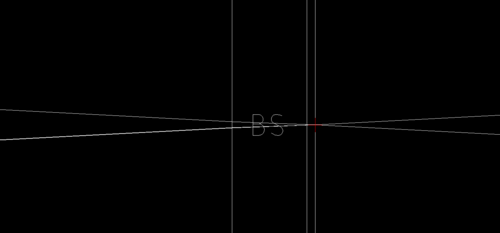
| I have created the long shoelaces 1 layout for cosmic explorer using gtrace, a slight modification from the shoelaces 1 layout design. I also modified the simulation code slightly to remove ghosting effects in the beamsplitter. Originally the python code specified that the HR and AR sides of the beamsplitter both have the same transmission/reflection. I modified this to the ideal case of: Refl_AR = 0, Trans_AR = 1. I have attached two images below to show the before and after effect of this modification. |
| Attachment 1: long_shoelaces1_desmos.JPG
|
|
| Attachment 2: AR_side_with_reflection.PNG
|
|
| Attachment 3: AR_side_without_reflection.PNG
|
|
|
333
|
Wed Feb 21 11:58:30 2024 |
Shane | Update | Cleanroom | cleanroom cleaning and particle count |
|
[Luke, Shane, Tyler]
cleaning cleanroom and particle count
- 11:50 am: ran zero count test on particle counter
- 11:55 am: started particle count
- zone 3:
- 0.3 u: 1787
- 0.5 u: 581
- 1.0 u: 166
- zone 4:
- 0.3 u: 623
- 0.5 u: 290
- 1.0 u: 124
- 12:17 pm: began surface check and wipedown, including softwalls
- 12:25 pm: started vacuuming the floor
- 12:36 pm: finished vacuuming the floor
- 12:44 pm: started mopping the floor
- 12:57 pm: finished mopping the floor
- 12:58 pm: started cleaning the buckets
- 12:59 pm: started mopping with IPA wipes
- 1:05 pm: finished mopping with IPA wipes
- 1:06 pm: changed sticky floor mats
- 1:08 pm: started particle count
- zone 3:
- 0.3 u: 1621
- 0.5 u: 581
- 1.0 u: 332
- zone 4:
- 0.3 u: 1080
- 0.5 u: 457
- 1.0 u: 249
|
|
332
|
Tue Feb 20 18:08:24 2024 |
Aiden | Update | General | Degassing the RGA |
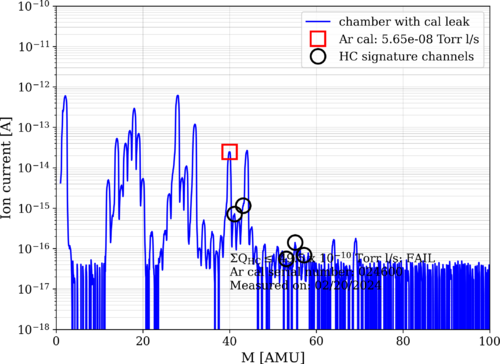
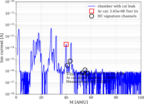
| I took an RGA measurement before and after degassing the RGA. Both data was taken with the Argon open. The pressure before taking data was 2.39 e-8 torr in the main volume. Note that the main chamber was fully valved off for the degas and the main chamber pressure quickly rose to e-6 torr. Further investigation of this rise should be done as this might be the main culprit for the leaking. |
| Attachment 1: bake11_240220_Elements_postdegas_ArO.png
|
|
| Attachment 2: bake11_240220_Elements_predegas_ArO.png
|
|
|
331
|
Tue Feb 20 11:31:49 2024 |
Tyler | Update | Cleanroom | Garment Cabinet Door Replacement |
| [Luis, Luke, Pooyan, Tyler]
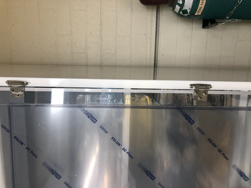
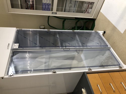
The replacement door for the HEPA garment cabinet arrived last week, and was installed on Thursday. However, it looks like there's a small gap between the door and where the hinge is attached to the cabinet frame. No screws were provided with the replacement door. If we want to perform any adjustments, we have to be very careful; the screws break very easily.
|
| Attachment 1: image_67190529.JPG
|
|
| Attachment 2: image_67177473.JPG
|
|
|
330
|
Tue Feb 20 08:01:30 2024 |
Jon | Infrastructure | General | Power and network equipment installed in 1129 rack |
| [Jon, Tyler, Pooyan, Luis, Luke, Peter]
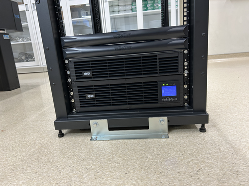
On Thursday we installed the power conditioning/distribution equipment and networking equipment in the new 1129 rack. The hardware is identical to the setup in the 1119 rack and includes:
- Tripp Lite SU5KRT3UTF - 208V, 5kVA on-line UPS with 120V transformer
- CyberPower PDU20M2F12R - metered power distribution unit, (14) NEMA 5-20R
- Ubiquiti USW-Pro-48 - 48 port 10Gbps network switch
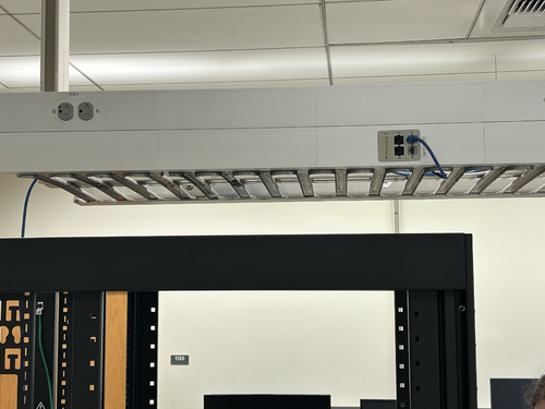
The UPS is connected to a 208V NEMA 6-30R outlet in the overhead cable tray, which is on the building's "standby" (backup power) circuit. An 8-ft L6-30 extension cord has been ordered to permanently run the power cable through the cable tray.
The network switch will be connected to a Cat6 cable that was recently run by ITS from the 1119 rack, allowing the lab's LAN to be extended into 1129. This Ethernet link remains to be tested.
| Quote: |
Server Rack Installation
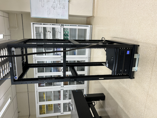
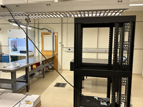
A new Tripp Lite 42U open-frame rack was laid in place in 1129 and anchored to the floor (see attachment 1). This rack will house all of our general-purpose and simulation computers, which will be relocated from the 1119 rack at a later time.
|
|
| Attachment 1: IMG_0924.jpeg
|
|
| Attachment 2: IMG_0925.jpeg
|
|
| Attachment 3: IMG_0921.jpeg
|
|
| Attachment 4: IMG_0922.jpeg
|
|
|
329
|
Mon Feb 19 14:40:21 2024 |
Shane | Update | CDS | MEDM screen for FROSTI temp readouts |
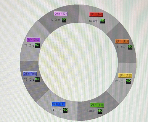
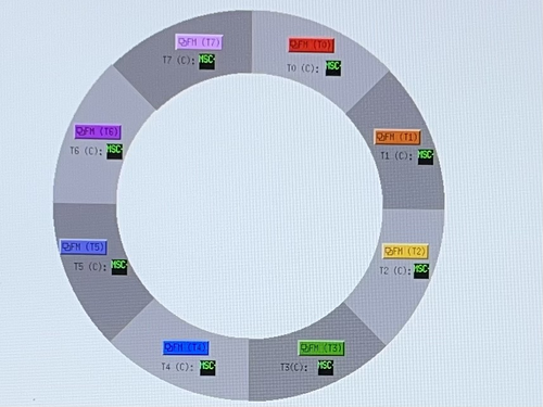
| Here's the latest draft of the MEDM screen for the FROSTI heating elements' temperature readouts. Note that the MEDM screen isn't actually this grainy, this just happens to be a photo of the lab monitor's screen off a phone. |
| Attachment 1: IMG_6094.jpeg
|
|
| Attachment 2: IMG_6092.jpeg
|
|
|
328
|
Mon Feb 19 14:17:50 2024 |
Aiden | Update | VAC | Heater Element RGA Scan |
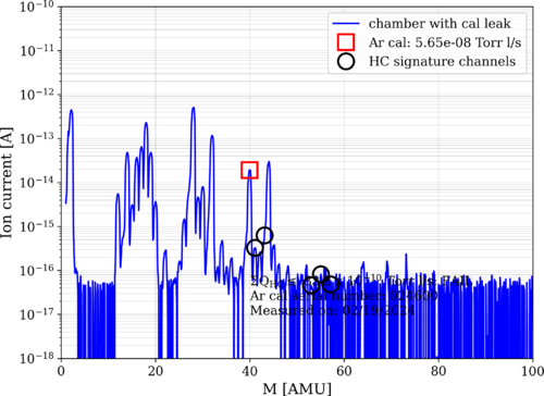
| Three days after the completion of Bake 11, the Heater elements RGA scan looks much cleaner. The HC level is back down to 33 e-10 torrl/s with the pressure at 2.13 e-8 torr. I could not take a= scan with the Argon closed as it was left open during the bake and not closed since then. |
| Attachment 1: bake11_240219_Elements_ArO.png
|
|
|
327
|
Fri Feb 16 18:37:28 2024 |
Jon | Update | VAC | Bake ended 6:23 pm |
I ended the bake of the UHV system (that began on Monday) at 6:23 pm today by switching OFF both PID controllers. The heaters elements were run at max power (24 V DC / 200 mA per element) during this bake, and I left them powered at the same level.
At the time, the instrument readings were as follows:
- Left high-limit controller: 138 C
- Right high-limit controller: 128 C
- Left PID controller: 100 C
- Right PID controller: 100 C
- Main volume pressure: 8.17e-7 Torr
- RGA volume pressure: 4.63e-7 Torr
|
|
326
|
Tue Feb 13 13:02:41 2024 |
Pooyan | Update | Interferometer Simulations | Cacity sacn of Fabry-Perot |
| Created a simple model of Fabry-Perot cavity in SIS, and did a cavity scan. Total power in the cavity, 00 mode, and HOMs is measured. |
| Attachment 1: IFOSim_update_2_13_24.pdf
|

|
|
325
|
Tue Feb 13 12:34:04 2024 |
Aiden | Update | VAC | VAC Heating System Update |
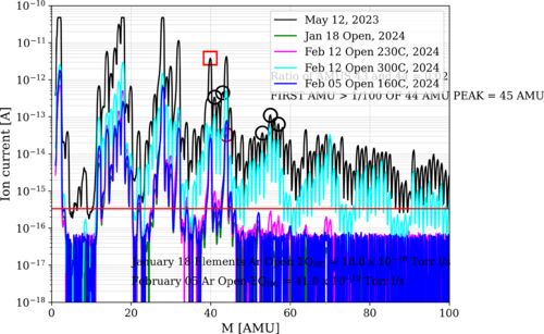
| Here is an overlay with for all the heating steps done with the heater elements. |
| Attachment 1: bake10_240118_Elements_ArO.png
|
|
|
324
|
Tue Feb 13 12:26:23 2024 |
Tyler | Update | Interferometer Simulations | BS Code Update |
I reproduced Cao's CE beamsplitter code (see below for example plots). I received the current info on the beamsplitter parameters for A+ and A# from GariLynn also. The next steps are to perform a similar power loss analysis on the anticipated A# beamsplitter. |
| Attachment 1: thickness1.pdf
|

|
| Attachment 2: bs_opd_homloss_h6cm_w2cm.pdf
|

|
|
323
|
Tue Feb 13 11:54:45 2024 |
Tyler | Configuration | FLIR | In-Air Optical Test Configuration |
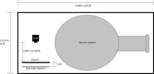
Below is the proposed schematic for FROSTI optical testing, chosen so enough space is allotted for prototype assembly.
Steps to be taken include:
- Reconstruct FLIR staging apparatus
- Move test mass stand-in to cleanroom
- Mark FLIR camera position on cleanroom optical table at correct distance
- Run ethernet cable into cleanroom
- Move FLIR aside to allow for more assembly space
- Upon assembly completion, reposition FLIR onto optical table again
Tentative plan is to begin setup early next week. |
| Attachment 1: In-air_optical_test_sketch.png
|
|
|
322
|
Tue Feb 13 04:05:32 2024 |
Michael | Update | Interferometer Simulations | Shoelaces 1 Layout Simulated in GTrace |
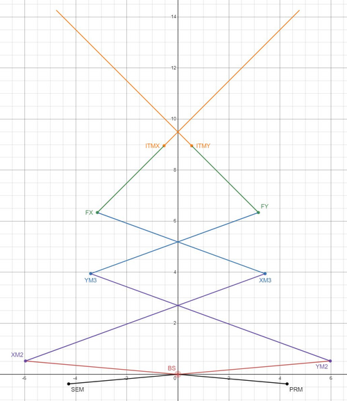
| I've worked on and have completed a first simulation of Cosmic Explorer's Shoelaces 1 layout. This is based off of Pooyan's original work with Gtrace much like the Long Crab 1 layout I worked on last week. This layout will allow me to quickly created the alternate shoelaces layouts. I've included an image of the dxf, and a desmos model for reference. |
| Attachment 1: shoelaces1_dxf.JPG
|

|
| Attachment 2: shoelaces1_desmos.JPG
|
|
|
321
|
Tue Feb 13 01:26:30 2024 |
Peter | Update | Interferometer Simulations | CARM Power Simulations |
| Cao's simulations of the circulating power and gouy phase through a single arm cavity of the interferometer have been reproduced. Images of the plots can be shown in the pdfs attached. There are approx. 400 lines in this code (scenario_3_carm) that produces these plots. This code also calls on a separate code source file (thermal_models) that defines many of the functions used in this main simulation. The thermal_models file consists of over 1000 lines. More work needs to be done to fully understand and document the scripts. |
| Attachment 1: Scenario_3_CARM.pdf
|

|
| Attachment 2: Scenario_3_CARM_Gouy.pdf
|

|
|
320
|
Mon Feb 12 17:35:47 2024 |
Aiden | Update | VAC | Heater Element RGA Scan |
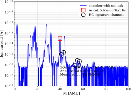
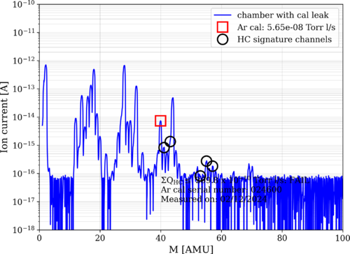
| Took more RGA data before and after increasing the heater elements to 300 degC and before heating them up.
Started Bake 11 as well to hopefully prevent any hydrocarbons from getting captured by the room temperature walls of the chamber. The PID controllers were set to 100C. |
| Attachment 1: bake10_240212_Elements_ArO.png
|
|
| Attachment 2: bake10_240212_Elements_ArC.png
|
|
| Attachment 3: bake10_240212_Elements_300C_ArC.png
|
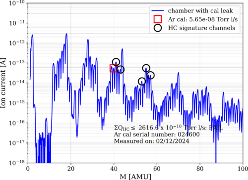
|
|
319
|
Thu Feb 8 17:37:48 2024 |
Aiden | Update | VAC | Heater Element RGA Scan |
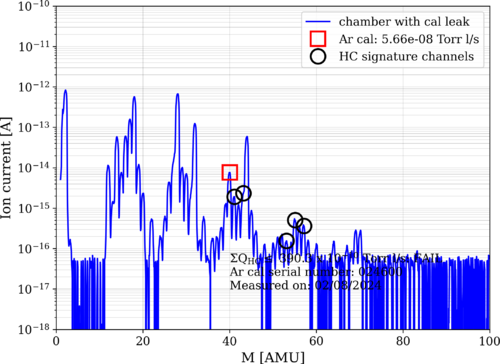
| Took more RGA data now that the heaters are powered by 18V. The pressure of the system during the data taking was 3.8 e-8 torr. The RGA scans seem to have gotten worse as well with this power increase. |
| Attachment 1: bake10_240208_Elements_ArO.png
|
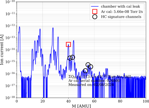
|
| Attachment 2: bake10_240208_Elements_ArC.png
|
|
|
318
|
Wed Feb 7 12:43:22 2024 |
shane | Update | Cleanroom | cleanroom particle counts (full 5 zone measurement) |
| Here's today's full 5 zone measurement of the cleanroom. Everything is back under the requirement. |
| Attachment 1: 24.png
|
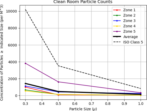
|
|
317
|
Tue Feb 6 22:40:25 2024 |
Michael | Update | Scripts/Programs | Long Crab 1 Design Created In Gtrace |
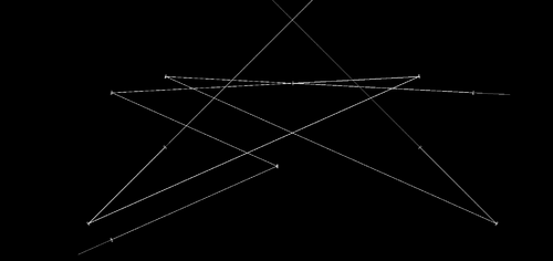
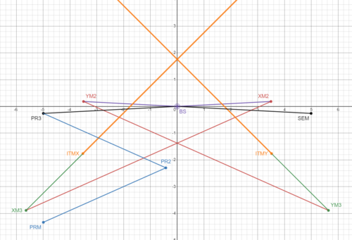
| Worked on and completed the python code for the simulation of the Long Crab 1 layout for Cosmic Explorer basing off of Pooyan's original work with the Crab 1 layout. From here I'll look into creating the shoelaces layouts. |
| Attachment 1: Long_Crab1.png
|
|
| Attachment 2: long_crab_1_desmos.PNG
|
|
|
316
|
Mon Feb 5 14:17:52 2024 |
Aiden | Update | VAC | Heater Element RGA Scan |
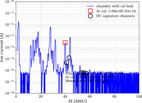
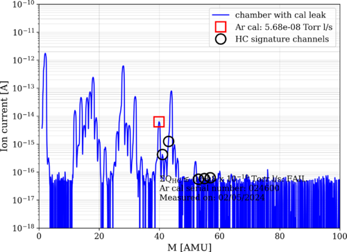
| Here are the new RGA scans for the powered Heater elements. The pressure at the time of taking data was 2.88 e-8 torr. The HC levels are at 40 e-10 torrl/s which is not bad but still higher than the lowest we have recorded. |
| Attachment 1: bake10_240205_Elements_ArO.png
|
|
| Attachment 2: bake10_240205_Elements_ArC.png
|
|
|
315
|
Fri Feb 2 19:18:24 2024 |
shane | Update | Cleanroom | cleanroom cleaning and particle count |
|
[Aiden, Shane, Luis, Luke]
cleaning cleanroom and particle count
|
|
314
|
Fri Feb 2 19:08:20 2024 |
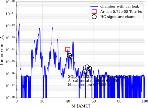
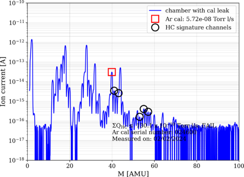
Aiden | Update | VAC | 1st Hot Element RGA Scan |
| Here are the measurements for the RGA scan of the elements while on at around 160C. The pressure of the chamber during the test was 4.12 e-8 torr. |
| Attachment 1: bake10_240202_Elements_ArC.png
|
|
| Attachment 2: bake10_240202_Elements_ArO.png
|
|
|
313
|
Fri Feb 2 16:56:56 2024 |
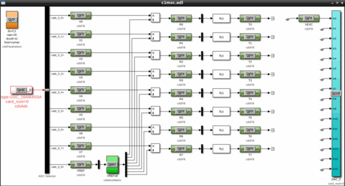
Jon | Update | CDS | RTS model implemented for FROSTI RTD readouts |
Summary
Today I finished implementing an RTS model to read out the integrated FROSTI RTDs (temperature sensors) via the CyMAC. The model is named "MSC" and is located at cymac:/opt/rtcds/usercode/models/c1msc.mdl. We successfully tested it with the heater elements operating in vacuum at low power (12 VDC), finding them to reach an average steady-state temperature of 160 C.
From the cymac host, the MEDM control screen can be accessed with the terminal command "sitemap" (from any directory).
Measurement Technique
Each FROSTI heater element [299] contains an internal two-wire RTD placed near the front emitting surface, which enables the temperature of the blackbody emitter to be directly monitored. From the measured temperature and the emissivity of the uncoated aluminum nitride surface (known to be ~1 in the IR), the radiated source-plane power can also be estimated.
The resistance of each RTD is measured via a ratiometric technique. The RTDs are powered in series with a 1 kΩ reference resistor located inside the readout chassis [305], whose temperature is not changing. The signal is obtained by taking the ratio of the voltage difference across each individual RTD to the voltage difference across the reference resisitor. The advantage of this technique is that the ratio of the voltage differences is insensitive to changes in the current through the resistors (since they are all in series; see [271] for wiring diagram).
Implementation Detail
The signal flow is shown in Attachment 1. The eight RTD signals enter through ADC channels 0-7, along with the reference resistor signal on channel 8. The first set of filter modules apply a calibration gain to convert the signals from raw ADU counts to units of input-referred voltage. The ratio of each RTD signal to the reference resistor signal is then taken. The second set of filter modules multiply the voltage-difference ratios by the resistance of the reference resistor, 1 kΩ ± 0.01%, to obtain the RTD resistances in physical units of ohms.
Finally, a freeform math module is used to invert the quadratic relation between each RTD's resistance and temperature. The final signals passed to the third set of filter modules are the RTD temperatures in physical units of degrees C. The temperatures of the tungsten RTDs are estimated assuming TCR coefficients of A=0.0030 C-1 (±10%) and B=1.003E-6 C-2, which were provided by the manufacturer.
One DAC channel is used to provide the excitation voltage for the RTD measurement, which is visible on the far right of the control screen. At its maximum output voltage of +10 V, the DAC can drive a maximum current of 10 mA. |
| Attachment 1: sitemap_screen.png
|
|
|
312
|
Wed Jan 31 14:37:26 2024 |
Shane | Summary | CDS | path directions for CyMAC model and parts library |
| Path to cds parts library in Matlab simulink: /usr/share/advligorts/src/src/epics/simLink. File name CDS_PARTS.mdl
Path to user models: /opt/rtcds/usercode/models, using file name c1msc.mdl |
|
311
|
Tue Jan 30 11:36:19 2024 |
Tyler | Update | Electronics | RTD Chassis |
| Quote: |
After updating the wiring in the RTD Chassis, a signal is now seen at each ADC input. However, there seems to be a discrepancy between the voltages I measured out with the multimeter (see below). Next steps include:
- Finish final debugging
- Calibrate ADC inputs with known voltage source (likely to use DAC).
Voltage Readings:
RTD 1: 0.576 V
RTD 2: 0.578 V
RTD 3: 0.598 V
RTD 4: 0.563 V
RTD 5: 0.477 V
RTD 6: 0.463 V
RTD 7: 0.456 V
RTD 8: 0.491 V
Reference Resistor: 5.463 V
Total Voltage: 9.665 V |
After further modification of the RTD readout chassis (i.e. adding resistors, placing reference resistor in front of RTDs), here are the following direct measurements:
RTD 1: 0.484 V
RTD 2: 0.486 V
RTD 3: 0.503 V
RTD 4: 0.474 V
RTD 5: 0.495 V
RTD 6: 0.483 V
RTD 7: 0.476 V
RTD 8: 0.510 V
Reference: 5.847 V
Here are the Cymac signal readings:
RTD 1: 74
RTD 2: 67
RTD 3: 73
RTD 4: 45
RTD 5: 82
RTD 6: 75
RTD 7: 70
RTD 8: 71
Reference: 884
The one (possible) discrepancy here is the readout for RTD 4 via Cymac, since it's signal reading is ~30 counts lower than the others. I do not believe this is a wiring issue due to the direct measurements taken. |
|
310
|
Tue Jan 23 12:17:41 2024 |
Tyler | Update | Electronics | RTD Chassis |
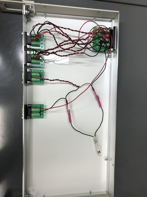
After updating the wiring in the RTD Chassis, a signal is now seen at each ADC input. However, there seems to be a discrepancy between the voltages I measured out with the multimeter (see below). Next steps include:
- Finish final debugging
- Calibrate ADC inputs with known voltage source (likely to use DAC).
Voltage Readings:
RTD 1: 0.576 V
RTD 2: 0.578 V
RTD 3: 0.598 V
RTD 4: 0.563 V
RTD 5: 0.477 V
RTD 6: 0.463 V
RTD 7: 0.456 V
RTD 8: 0.491 V
Reference Resistor: 5.463 V
Total Voltage: 9.665 V |
| Attachment 1: rtd_updated_circuitry.jpg
|
|
|
309
|
Thu Jan 18 18:06:49 2024 |
shane | Update | Cleanroom | cleanroom 5 zone particle count measurement |
| Here's today's full five zone measurement of the cleanroom |
| Attachment 1: 24.png
|

|
|
308
|
Thu Jan 18 15:13:37 2024 |
Aiden | Update | VAC | VAC Heating System Update |
| [Aiden]
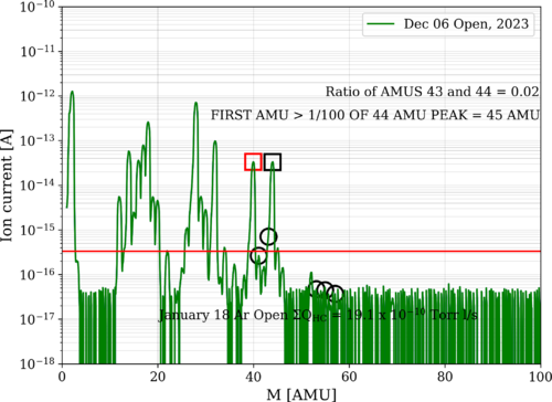
Took more data today and the chamber and elements are showing an even lower HC level than we have gotten before. It is safe to say that the elements are not contaminated and out gassing HC into the chamber. |
| Attachment 1: bake10_240118_Elements_ArO.png
|

|
| Attachment 2: January_18_Ar_Open_Elements_Analyzed.png
|
|
|
307
|
Wed Jan 17 15:47:49 2024 |
Aiden | Update | General | Resistors for Heater Elements |
| Power Res (Ohm) RTD Res (Ohm)
Heater 1= 73.6; 81.8
Heater 2= 70.4; 82.1
Heater 3= 71; 84.5
Heater 4= 71.5; 80
Heater 5= 70.5; 81.7
Heater 6= 72; 79.4
Heater 7= 69.2; 78.2
Heater 8= 71.1; 84.2 |
|
306
|
Tue Jan 16 16:11:41 2024 |
Aiden | Update | VAC | |
| [Aiden,Luis]
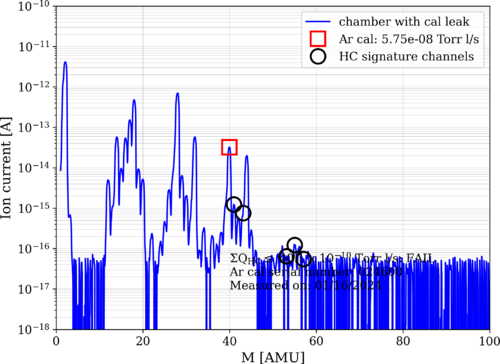
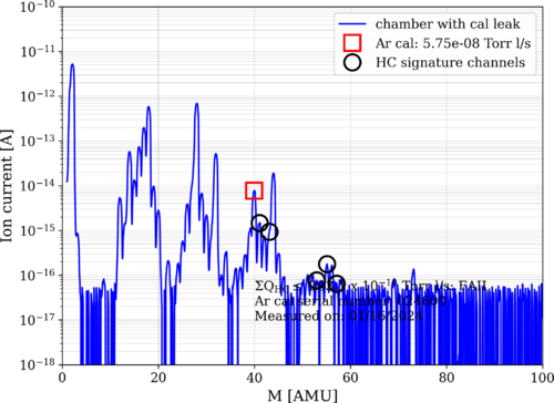
Below is the data for the most recent bake. I believe the chamber is cleaner than it is actually showing as the RGA data was still getting lower while the data was being taken. I will take the data again tomorrow just in case. Still, the data shows that the chamber is basically as clean as it was before bake 10 and this means further power testing can proceed.
Helium leak tested the chamber again today to check if the sealant changed anything. The two primary target flanges from last time have improved significantly with the flange from the RGA on the cross now being below 2e-14. While the turbo pump flange was leaking at a rate of 4e-13. Much better than what it has been before. |
| Attachment 1: bake10_240116_Elements_ArO.png
|
|
| Attachment 2: bake10_240116_Elements_ArC.png
|
|