| ID |
Date |
Author |
Type |
Category |
Subject |
|
507
|
Sat Feb 1 17:25:52 2025 |
Luke | Summary | General | Cleanroom cleaning |
[Luke, Cece, Luis]
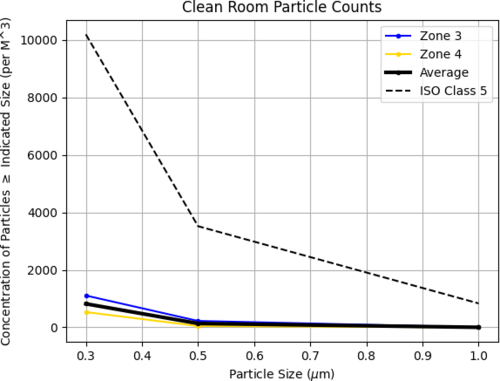
Particle Count Measurements:
- Pre-cleaning (12:15 PM):
- Zone 3:
- 0.3 µm: 1325
- 0.5 µm: 265
- 1.0 µm: 0
- Zone 4:
- 0.3 µm: 618
- 0.5 µm: 132
- 1.0 µm: 44
- Started Cleaning (3:20 pm)
- Finished Cleaning (4:20 pm)
- Post-cleaning (4:35 PM):
- Zone 3:
- 0.3 µm: 1106
- 0.5 µm: 221
- 1.0 µm: 0
- Zone 4:
- 0.3 µm: 530
- 0.5 µm: 44
- 1.0 µm: 0
|
| Attachment 1: 20250131_particalcount.png
|
|
|
513
|
Sun Feb 16 16:45:18 2025 |
Luke | Update | General | Ringheater position optimization |
Over the last couple weeks I have been working on finding the optimal position of the ringheater's thermal profile.
Today I would like to give an update of where I am at and my next steps.
Using the python COMSOL interface I have been able to run and save deformation data sweeping through a great deal of potential combinations of widths and positions.
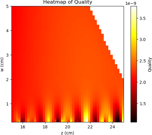
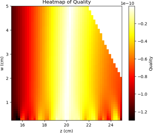
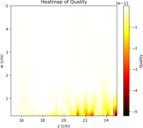
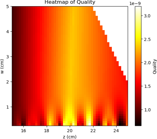
I then calculated their zernike coefficients and using a very simple "quality" function (02 - (40)*10 - (4-4)*10), where 02 stands for the zernike mode of quadratic deformation, I was able to generate a heat map of comparing the "quality" verses the width and position used.
Seen below are four plots. The first is simply the 02 coefficient of the decomposition followed by the negative of 40 and 4-4 then the "quality."
This 'quality' function was an arbitrary choice on my part. I believe that my next step would either be defining a more useful function or using finesse to model the actual effects of this surface deformation. |
| Attachment 1: 02.png
|
|
| Attachment 2: _40.png
|
|
| Attachment 3: _4-4.png
|
|
| Attachment 4: 02_40_4-4.png
|
|
|
549
|
Tue Apr 8 10:47:10 2025 |
Liu | Update | General | Test Mass Thermal State Decoder Update |
|
| Attachment 1: Update.pdf
|

|
|
597
|
Tue Jun 24 12:45:16 2025 |
Tyler | Update | General | Updated ADC spectra |
| [Tyler]
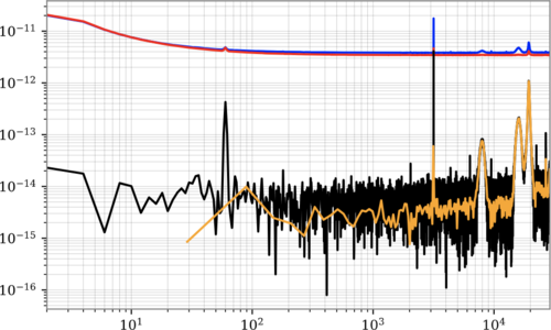
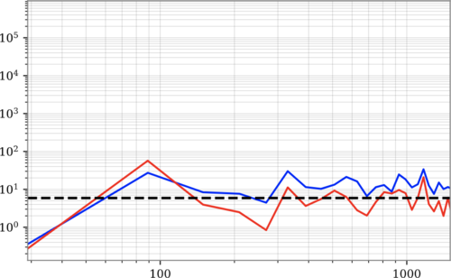
Updated ADC noise spectra measurements using diaggui.
NOTE: Will update plots with proper axes |
| Attachment 1: csd_spec.png
|
|
| Attachment 2: chi_sq.png
|
|
|
605
|
Mon Jul 7 17:44:04 2025 |
Tyler | Update | General | Lab Organization |
| [Tyler, Pooyan, Ma, Cece, Luke, Luis, Christina, Maple]
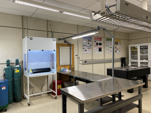
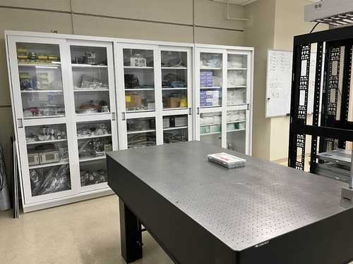
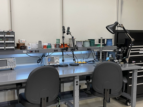
After acquiring some new equipment for the labs, a few of us spent time on Thursday and Friday sorting through everything and storing them into their appropriate places. New vacuum parts, power supplies, cables, and much more were included. The rooms are now ready for the lab tours commencing Tuesday afternoon. |
| Attachment 1: IMG_1874.jpg
|
|
| Attachment 2: IMG_1872.jpg
|
|
| Attachment 3: IMG_1871.jpg
|
|
|
640
|
Tue Sep 2 18:33:38 2025 |
Liu | Infrastructure | General | New lab room 1125 layout and measurement |
Action items for facilities
- Ceiling lights replacement
- Fume hood cleaned and refurbished
- Sink countertop cleaning
- Floor cleaned and waxed
-
|
| Attachment 1: 1125.pdf
|

|
|
662
|
Thu Nov 20 12:40:47 2025 |
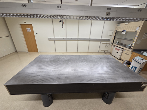
Xuesi Ma | Infrastructure | General | Room 1125 Optical Table |
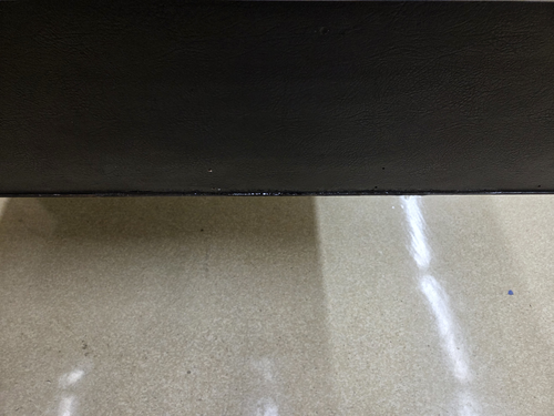
Cleaned off the tapes on the optical table with acetone. |
| Attachment 1: 1651.jpg
|
|
| Attachment 2: 1650.jpg
|
|
|
73
|
Wed Apr 19 17:39:50 2023 |
Pamella | Update | FLIR | FLIR project |
FLIR project updates- Initial tests
- 10:00: Starting test in position 2 cm to the black wall.
- Parameters : 0,305 A, 05,5 V and the temperature inside the mirrors 141,8°C.
- 10:23 Finished this first tried and take snap. The image is attached below.
- The name for the picture for this tried is “AcquisitionImage(Apr-19-2023_10 23)”.
- 10:37. Starting test in another position now 3 cm distance to the black wall ( this is more close than the original position.)
- Parameters : 0,348 A, 05,5 V and the temperature inside the mirrors 160,3°C.
- 10:57 Finished this second tried and take a snap. The image is attached below.
- The name for the picture for this tried is “AcquisitionImage(Apr-19-2023_10 57)”.
- 11:03 Starting test another position 1.3 cm distance to black wall.
- Parameters : 0,347 A, 05,5 V and the temperature inside the mirrors 158,7°C.
- 11:18 Finished this second tried and take a snap. The image is attached below.
- The name for the picture for this tried is “AcquisitionImage(Apr-19-2023_11 18)”.
The next step should be fix the problem with the shape (aluminum foil lid).
|
| Attachment 1: AcquisitionImage(Apr-19-2023_10_23)(1).jpg
|
(1).jpg.png)
|
| Attachment 2: AcquisitionImage(Apr-19-2023_10_57)_(1).jpg
|
_(1).jpg.png)
|
| Attachment 3: AcquisitionImage(Apr-19-2023_11_18)_(2).jpg
|
_(2).jpg.png)
|
|
75
|
Fri Apr 21 15:21:18 2023 |
Pamella | Update | FLIR | |
FLIR project updates
- 01:50 pm: Starting test position 34 mm distance to black wall.
- Parameters : 0.100 A, 1.5 V and the temperature inside the mirrors 40°C.
- 2:09 pm : Finished the test and figured out this position it is too far the black wall so now we change for more close position.
- 2:17 pm: Starting test in another position: 10 mm distance to the black wall( this measurement is between the black wall and the aluminum lid)
- 2:26 pm : Finished this second tried and take a snap. The image is attached below.
- The name for the picture for this tried is “AcquisitionImage(Apr-21-2023_14 26)”.
Note: The second tried the temperature didn't up more than 40°C for 8 minutes so I change the current for a few seconds.
I started with 0.98 A with 1.7 V and up until 0.350 A with 2.5 V, just for a few seconds and in this way the temperature up to 72°C and I get the snap.
The next step should be understand the problem with the shape and work in changes for get the triangle in the FLIR image. |
| Attachment 1: AcquisitionImage(Apr-21-2023_14_26).jpg
|
.jpg.png)
|
|
104
|
Mon May 22 17:08:50 2023 |
Pamella | Update | FLIR | FLIR project - Installing the mask. |
[Pamella]
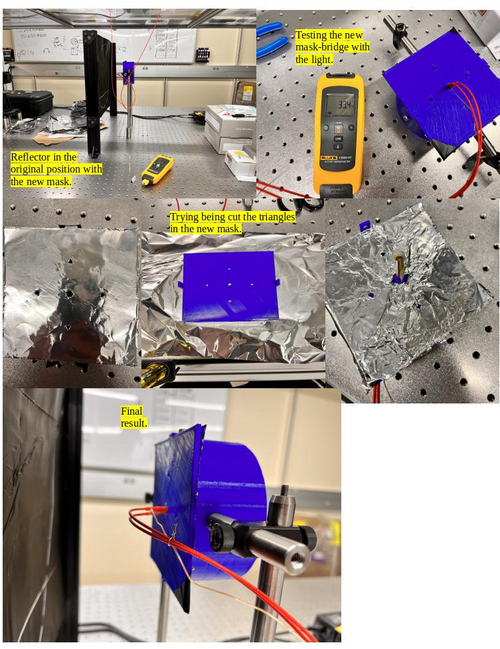
- The new mask for the reflector.
- 1:40 pm: Started reconfiguration on the FLIR camera project. Changed the old bridge for the new mask-bridge.
- 2:00 pm: Started figure out the best way to cutting the aluminum foil with the new mask. Unfortunately, I had been some problems for cutting the perfect shape triangles with the mask because the size inside the triangle is different (smaller) than cutter/knife, so is not able to do the cut with precious and carefully then maybe I need other tool for this job. Also I tried use the scissor, didn't work. However, just for the initial testing I worked with the not perfect triangles shape.
- 2:49 pm: Started installing/attaching the light in the mask.
- 3:21 pm: Finished installing the light in the mask-bridge.
- 3:22 pm: Started testing the current and voltage in the new mask-bridge for make sure the light cable is working well.
- 3:25 pm: Started measurement the resistance with multimeter.
- 3:29 pm: The measurement looks fine. The multimeter show us 14.1 Ω;
- 3:38 pm: Started putting the reflector( with the mask attached) in front of the black wall.
- 3:44 pm: Started roll the testing with the python code to observer the behavior with this new mask. Parameters: 0.14 A and 1.9 V.
- 4:00 pm: Started snapping. Parameters: 0.13 A and 1.9 V. Final Temperature: 42.7 C.
- 4:02 pm: Started trying again with more current. Parameters: 0.16 A and 2.2 V.
- 4:36 pm: Started snapping. Parameters: 0.16 A and 2.2 V. Final Temperature: 50.3 C.
- 4:55 pm: For now, we can't see the triangles in the snap so i need do some changes.
- To do:
- Change the FLIR camera position for the other side on the table.
- Start the test without the black wall.
- Try a better tool to cut the triangles inside the 3D-mask.
|
| Attachment 1: Mask.jpg
|
|
| Attachment 2: AcquisitionImage(May-22-2023_16_35).jpg
|
.jpg.png)
|
| Attachment 3: AcquisitionImage(May-22-2023_16_01).jpg
|
.jpg.png)
|
|
105
|
Tue May 23 16:52:56 2023 |
Pamella | Update | FLIR | FLIR project - Reinstalling the mask and Reconfiguration FLIR position. |
[Pamella]
Reinstalling the mask and Reconfiguration FLIR position.
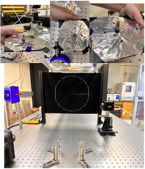
- Today i change the aluminum foil inside the 3D mask. After some tries i was able to have a better shape for the triangles.
- I reinstalled the connections (the light with the thermometer point). Also i checked for the focal point inside the reflector, looks fine.
- I did a reconfiguration for the initial tests, without the black wall. I moved the FLIR camera and the Reflector-Mask for other position on the table.
To do:
- Start the test with the power current on.
- I need figure out a better position for the light cables because in front of the mask isn't a good position for us do measurement.
|
| Attachment 1: AcquisitionImage(May-23-2023_16_36).jpg
|
.jpg.png)
|
| Attachment 2: Reconfiguration.jpg
|
|
|
106
|
Wed May 24 14:06:27 2023 |
Pamella | Update | FLIR | FLIR project - Tests |
[Pamella]
Initial tests
- 10:30 am : Started trying take some test with the new position/configuration between the 3D reflector-mask and the FLIR camera.
- 10:41 am : Started running the python code and take a snap. Parameters: 0.10 A, 1.4 V.
- 10:50 am : Started take the snap.It is possible see the triangles, this is a good thing. Negative thing: The middle/center point for the light maybe would be some problems for the future measurements. Parameters: 0.10A, 1.4 V and 41 C.
- 11:00 am : Started working to better align the entire structure. And double-check the distance between the 3D reflector-mask and the FLIR camera, following the instructions in Cassidy's Final FLIR Project Report.
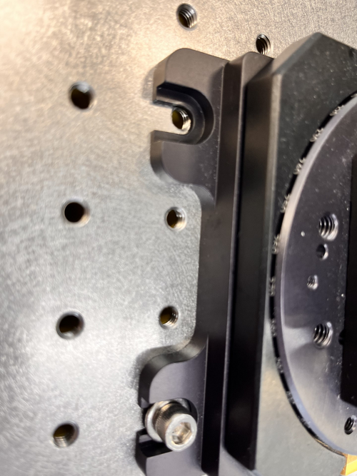
- 11:10 am : Difficult point: I tried to attach the complete FLIR camera to the table, but I had a problem to secure the four screws to the table, the distance is not completely compatible with the table stand. Yesterday I just put two screws in the diagonal position, it works fine, but it's not the correct position to work.
- 12:00 am : Note: Two triangles take more long time to come back a not (low) irradiation position (east and south point).
- 2:00 pm : Started running the python code again.
- Parameters: 0.13 A 1.8 V.
- 2:30 pm: Started take snap. Parameters: 0.13 A, 1.8 V and 49.1 C
- 3:00 pm: Note: This time every triangles was able to come back a low irradiation position.
|
| Attachment 1: AcquisitionImage(May-24-2023_10_50).jpg
|
.jpg.png)
|
| Attachment 2: thumbnail_IMG-7146.jpg
|
|
| Attachment 3: AcquisitionImage(May-24-2023_14_30).jpg
|
.jpg.png)
|
|
108
|
Tue May 30 14:51:27 2023 |
Pamella | Update | FLIR | New 3D mask - Bigger triangles shapes. |
[Pamella]
Change the 3D mask
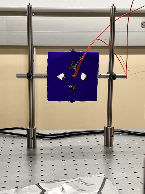
- Started removing the old mask in the reflector.
- Started cutting the new aluminum lid for the new 3D mask and assembling in the 3D mask.
- Started doing the new cable connections for the light.
- Started testing the resistance in the new cable connections. The multimeter show us 14.2 Ω.
- Started attaching the mask with the light and the thermometer sensor.
- Started assembling the 3D mask in the reflector.
- Started the initial tests.
- 2:00 pm: Started testing the new mask. Parameters: 1.4 V 0.1A and 27 C
- 2:38 pm: Started taking snap. Final parameters:1.4 V 0.1A and Temperature: 39.9 C
- Started doing some adjustments in the triangles shapes for the futures tests.
|
| Attachment 1: AcquisitionImage(May-30-2023_14_38).jpg
|
.jpg.png)
|
| Attachment 2: thumbnail_IMG-7303.jpg
|
|
|
112
|
Wed May 31 16:55:55 2023 |
Pamella | Update | FLIR | FLIR- Focus distance |
[Pamella and Tyler]
- We changed the FLIR Focus Distance for around 0.55 m.
- Note: The old focus distance was 1.3 m.
- We tested this new focus distances and looks good. I attached a snap below.
Parameters: 0.1 A , 1.5 V and 38.4 C.
|
| Attachment 1: AcquisitionImage(May-31-2023_16_40).jpg
|
.jpg.png)
|
| Attachment 2: thumbnail_IMG_7310.jpg
|
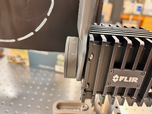
|
|
113
|
Thu Jun 1 14:41:36 2023 |
Pamella | Update | FLIR | FLIR project - Test without the black wall. |
[Pamella]
Test without the black wall.
General test:.
- 11:15 am : Started running the code. Parameters: 0.11 A, 1.9V and focus distance around 0.55m.
- 11:28 am : Started snapping the screen. Parameters: 0.12 A, 1.8V and 44.1 C .
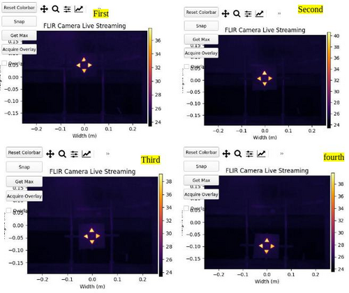
First trying:
- 01:18 pm : Started testing and collection data. Parameters: 0.09 A, 1.4V. Reference position: (0,0).
- 01:28 pm : Started snapping the screen. Parameters: 0.10 A, 1.5V and 37.9 C. Reference position: (0,0).
Second trying:
- 01:34 pm : Started testing and collection data. Parameters: 0.08 A, 1.4V. Reference position: (0,-0.10).
- 01:44 pm : Started snapping the screen. Parameters: 0.09 A, 1.7V and 35.8 C. Reference position: (0,-0.10).
Third trying:
- 01:50 pm : Started testing and collection data. Parameters: 0.08 A, 1.3V. Reference position: (0,-0.05).
- 02:00 pm : Started snapping the screen. Parameters: 0.09 A, 1.4V and 35.4 C. Reference position: (0,-0.05).
Fourth trying:
- 02:04 pm : Started testing and collection data. Parameters: 0.09 A, 1.3V. Reference position: (0,0.05).
- 02:14 pm : Started snapping the screen. Parameters: 0.11 A, 1.6V and 41.7 C. Reference position: (0,0.05).
Note: So today i tried collecting data for every possible position in Y (height) way for starting analyses and compares the triangles shapes. I realize maybe we get a problem because i keep the same time in every try but the final temperature and the parameters change every time, so i will try do a better system to keep the parameters equal, maybe i can wait the reflector be back to a normal temperature after every test or keep the system on all the time and just change the reflector position. I pretty sure this was the problem.
|
| Attachment 1: thumbnail_IMG_7316.jpg
|
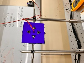
|
| Attachment 2: AcquisitionImage(Jun-01-2023_14_14).jpg
|
.jpg.png)
|
| Attachment 3: thumbnail_IMG_7320.jpg
|
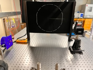
|
|
114
|
Fri Jun 2 14:28:40 2023 |
Pamella | Update | FLIR | FLIR project - Test without the black wall. |
[Pamella]
Test without the black wall.
Note: So today i collected data for some positions in axis Y (height) for starting analyses and compares the triangles shapes. I tried keep the same parameters every time.
First position:
- 01:20 pm : Started testing and collection data. Parameters: 0.10 A, 1.6V. Reference position: (0,0.05).
- 01:30 pm : Started snapping the screen. Parameters: 0.10 A, 1.6V and 37.7 C. Reference position: (0,0.05).
Second position:
- 01:34 pm : Started testing and collection data. Parameters: 0.10 A, 1.6V Reference position: (0,0).
- 01:44 pm : Started snapping the screen. Parameters: 0.10 A, 1.6V and 40.6 C. Reference position: (0,0).
Third position:
- 01:50 pm : Started testing and collection data. Parameters: 0.10 A, 1.6V. Reference position: (0,-0.05).
- 02:00 pm : Started snapping the screen. Parameters: 0.10 A, 1.6V and 39.1C. Reference position: (0,-0.05).
Fourth position:
- 02:03 pm : Started testing and collection data. Parameters: 0.10 A, 1.6V. Reference position: (0,-0.10).
- 02:13 pm : Started snapping the screen. Parameters: 0.10 A, 1.6V and 39.6 C. Reference position: (0,-0.10).
|
| Attachment 1: 1Axis_y___tests.jpg
|
|
|
117
|
Thu Jun 8 14:51:58 2023 |
Pamella | Update | FLIR | FLIR- Distance |
[Pamella, Tyler]
- Today we change the distance between the FLIR camera and reflector (3D-Mask with mirrors and light). Now the distance is 0.2032 m.
- Note: This distance is just for take a snap most close possible but we need move again for a little far way because in this distance we can't move up and down the reflector for have data to compare.
|
| Attachment 1: AcquisitionImage(Jun-08-2023_14_33).jpg
|
.jpg.png)
|
| Attachment 2: thumbnail_IMG_7441.jpg
|
|
|
118
|
Mon Jun 12 12:15:10 2023 |
Pamella | Update | FLIR | FLIR- Take data in the closest point. |
[Pamella]
- Used the closest point possible for the reflector in front of the FLIR camera.
- 11:32 am : Turned on the electronic device (current on) for started taking data.
- 11:50 am: Started checking the temperature and the parameters.
- 12:04 pm: Started taking snap after waited for 30 minutes with the current on. Parameters: Current: 0.13A , Volt: 1.8V and Temperature: 51.4 C.
- Note: This snap is in the most close point possible, after that I should be change the reflector position and also the optical focus distance in the FLIR camera.
We can see, in the photo attached below, thought in this closest position the cable connect to reflector is a bit problem to take a good snap also the have issues to keep very uniform triangles (temperature) in the reflector.
- To do: I'll change the position on the light inside to see if the problem it is in the focal point inside the reflector (mirror).
|
| Attachment 1: AcquisitionImage(Jun-12-2023_12_04).jpg
|
.jpg.png)
|
|
125
|
Fri Jun 16 16:17:13 2023 |
Pamella | Update | FLIR | FLIR - Change the position |
[Pamella]
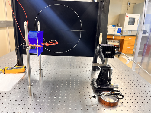
Today I change the distance between the FLIR camera and reflector (3D-Mask with mirrors and light). Now the distance is 0.3282 m.
- Note: In this distance is possible move up and down the reflector and take data to compare.
- The focal point inside the reflector keeping like little problem, every time I tried adjust this I got some triangles is not with "perfect emission" (looks like different than the others). Also if I move up or down the focal point inside the reflector have some issues as well.Therefore I am working on that.
|
| Attachment 1: IMG-7637.jpg
|
|
|
127
|
Mon Jun 19 11:20:57 2023 |
Pamella | Update | FLIR | FLIR - Fixed some problems |
[Pamella]
- 08:59 am: Turned on the electronic device (current on) for started taking data.
- 09:37 am: Tried understanding the error in the focal point. I realized the pillars was in the wrong place and because of that we got problems to keep the reflector in the correct position to FLIR focus.
- 09:58 am: Started checking the temperature and the parameters.Changed the pillars to the original position (0.5645m) just for checking with the problem was the pillar in the wrong place.
- 10:06 am: Changed the reflector to point (0.3282m) and now in the correct position for the pillars. Started take snap and collecting data. I moved up and down the reflector for got data to compare later.
- 10:37 am: Used the closest point possible for the reflector in front of the FLIR camera with the correct spot for the pillars.(0.2032m)
- 11:00 am: Started taking snap after kept the current on for a few hours. Parameters: Current: 0.10A , Volt: 1.3V and Temperature: 41.9 C.
- I attached below the snap in the most close point possible, now i can see a better photo and I think a fixed the problem about the focal point in the reflector for have more uniformity between the triangles, isn't perfect yet but now is just some adjustments. Furthermore after that I should be change the reflector position and also the optical focus distance in the FLIR camera and try use the black wall.
|
| Attachment 1: AcquisitionImage(Jun-19-2023_11_00).jpg
|
.jpg.png)
|
|
132
|
Fri Jun 23 15:47:06 2023 |
Pamella | Update | FLIR | Collecting data - Moving horizontal and vertical on screen. |
[Pamella]
- 02:09 pm: Turned on the device (current on)
- 02:42 pm: Started taking snap on position one (Reference point: 0,-0.062). Parameters:0.10A,1.5V,41.5C
- I took multiplier snap on the same position for compare after on data analyzes. I just wanted one/two minute break between the snaps. I did that same for every position.
- 02:55 pm: Started taking snap on position two (Reference point:-0.10,-0.062 ). Parameters: 0.10A,1.5v,43 C
- 03:01 pm: Started taking snap on position three (Reference point:0.05 ,-0.062). Parameters: 0.1A,1.4V,42.8C
- 03:07 pm: Started taking snap on position four (Reference point: 0.05,0.045). Parameters:0.10A,1.5V,43.6 C
- 03:15 pm: Started taking snap on position five (Reference point: 0,0.045). Parameters:0.10A, 1.4V, 44.1C
- 03:22 pm: Started taking snap on position six (Reference point: 0,0.045). Parameters: 0.10A,1.4V,43.3 C
- We can see in the photos attached below than have some differences between every position so I should be starting analyzes on that.
|
| Attachment 1: AcquisitionImage(Jun-23-2023_14_42).jpg
|
.jpg.png)
|
| Attachment 2: AcquisitionImage(Jun-23-2023_14_57).jpg
|
.jpg.png)
|
| Attachment 3: AcquisitionImage(Jun-23-2023_15_01).jpg
|
.jpg.png)
|
| Attachment 4: AcquisitionImage(Jun-23-2023_15_07)_(3).jpg
|
_(3).jpg.png)
|
| Attachment 5: AcquisitionImage(Jun-23-2023_15_15).jpg
|
.jpg.png)
|
| Attachment 6: AcquisitionImage(Jun-23-2023_15_22).jpg
|
.jpg.png)
|
|
135
|
Tue Jun 27 15:18:26 2023 |
Pamella | Update | FLIR | New data collection |
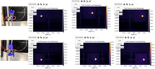
Yesterday, I did a new data collection. I could get a better data in this time and I realized than I need use some angle on the reflector for got a better shot. I need do that because the FLIR camera just is able to get the triangle shape for complete if I keep exactly in same line for center point on the camera but for the data now I need move the refletor to go up and go down. So wasn't working very well if I keep the reflector without angle.
Now I am using the refletor with a angle. In the more high part I turn the mask for look the table and in the lower part I turn the mask to look up. I attached a photo below for this configuration.
Also the processes to get the data was the same than I using last time, the only diference is now I just moved the pillar after get data for high position and lower position for the same reference point on the triangle shape.
Note: In most data it is impossible to keep the same parameter for current, voltage and temperature. Most have a small variation but not a big difference. For example: I got the temperature in the first position 46.8 °C and in the second position I got 47.1 °C, it's just an example. It's just so we know that we don't have the exact same parameters all the time. In my opinion this is not a problem because it is just a small variation.
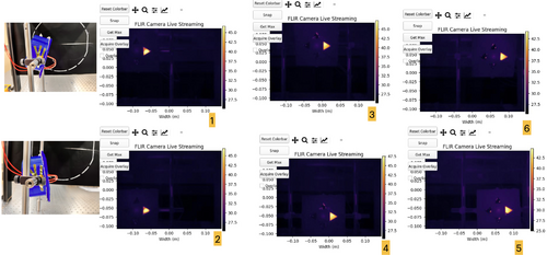
- 09:35 am: Turned on the device (current on). I wanted for 30 minutes before start get data.
- 10:05 am: Started taking snap on position one (Reference point: -0.10, 0.050). Parameters:0.11A,1.7V,46.8°C
- I took four snap on the same position for compare after on data analyzes. I just wanted one minute break between the snaps. I did the same for every position.
- 10:15 am: Started taking snap on position two (Reference point:-0.10,-0.050 ). Parameters: 0.11A,1.7V,47.1° C
- 10:22 am: Started taking snap on position three (Reference point:0.00 ,0.050). Parameters: 0.11A,1.6V,48.1°C
- 10:26 am: Started taking snap on position four (Reference point: 0.00,-0.050). Parameters:0.11A,1.6V,48 °C
- 10:32 am: Started taking snap on position five (Reference point: 0.05,-0.050). Parameters:0.11A, 1.6V, 48°C
- 10:37 am: Started taking snap on position six (Reference point: 0.05,0.050). Parameters: 0.11A,1.7V,47.6 °C
- We can see in the photos attached below every position also I am working in the analyzes.
|
| Attachment 1: FLIR_data.002.jpeg
|
|
| Attachment 2: FLIR_data_2.002.jpeg
|
|
|
139
|
Fri Jun 30 15:57:28 2023 |
Pamella | Update | FLIR | Data and python code update |
Updates: Problems with the emission intensity and python code.
- Yesterday I was working on get data from FLIR reflector but unfortunately we got some problems:
- I realized than if I move the reflector a to left or right the screen doesn't get data very well(I attached a photo below). This is a problem because our idea is have the same type of emission every part on screen. Tyler and I worked to tried fix that but don't had success.
- Dr. Richardson gave me the idea to move the FLIR camera to left or right (The same happens if I move up and down) and keep the refletor on the same position every time but unfortunately we got the same problem, the screen doesn't get data very well(I attached a photo below). Now I am working to tried fix that.
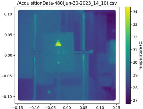
- Also I was able to work on the code to isolate the triangle shape for analyzes, I attached the image for that below.
|
| Attachment 1: isolation1-2.jpg
|
|
| Attachment 2: AcquisitionImage(Jun-29-2023_18_27)_(1).jpg
|
_(1).jpg.png)
|
| Attachment 3: AcquisitionImage(Jun-29-2023_18_38).jpg
|
.jpg.png)
|
| Attachment 4: AcquisitionImage(Jun-29-2023_18_39).jpg
|
.jpg.png)
|
|
140
|
Fri Jun 30 16:43:14 2023 |
Pamella | Update | FLIR | Updates: Small moving the FLIR camera |
[Pamella]
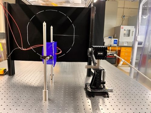
Today, I was able to make some adjustments to the FLIR camera angle, suggested by Dr. Richardson, and we got small possible movements keeping the same pattern in the shapes of the triangles. I have attached photos below. I was able to move left and right as well as up and down and it worked in four points that I marked on the table.
The only problem is that it only worked on a part of the screen, if I try to place it farther to the right or to the left, we are back to the same problem as yesterday.
|
| Attachment 1: AcquisitionImage(Jun-30-2023_16_23)_(3).jpg
|
_(3).jpg.png)
|
| Attachment 2: AcquisitionImage(Jun-30-2023_16_23)_(1)(1).jpg
|
_(1)(1).jpg.png)
|
| Attachment 3: AcquisitionImage(Jun-30-2023_16_24).jpg
|
.jpg.png)
|
| Attachment 4: AcquisitionImage(Jun-30-2023_16_22)_(1)(1).jpg
|
_(1)(1).jpg.png)
|
| Attachment 5: AcquisitionImage(Jun-30-2023_16_22)_(1).jpg
|
_(1).jpg.png)
|
|
143
|
Mon Jul 3 18:38:13 2023 |
Pamella | Update | FLIR | FLIR project |
[Pamella]
- I was able to work on the python code to do analysis on the FLIR-Reflector data.
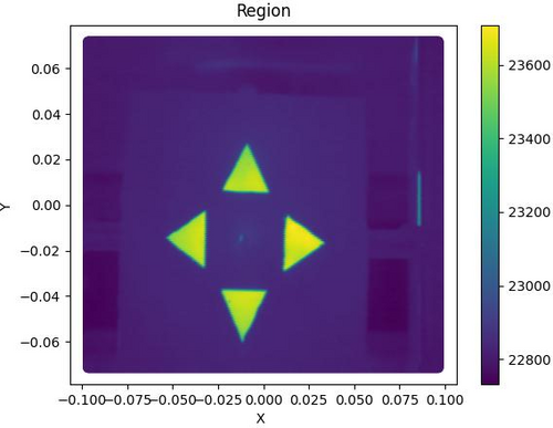
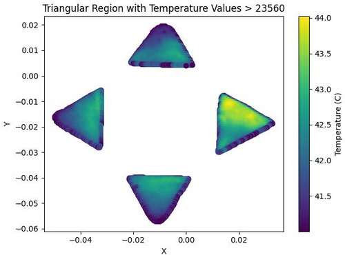
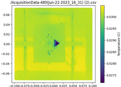
- I could plot images of total area (Tyler help me on that) with csv file and also could have isolation area for triangles. I have attached examples below. Just for now the images are of different data, so there are some differences in the shapes.
- I'm working on getting a complete analysis code to work with the different positions of the triangles and to be able to do out the statistical analysis.
- Also we keeping have problem to get good data if when we move the camera or the reflector on horizontal or vertical position. I am working a some ideas for that.
|
| Attachment 1: Region.jpg
|
|
| Attachment 2: triangular_region_temperature-2.jpg
|
|
| Attachment 3: heatmap.jpg
|
|
| Attachment 4: isolation1-4.jpg
|
|
|
144
|
Tue Jul 4 15:35:38 2023 |
Pamella | Update | FLIR | FLIR - reflexion problem |
| [Pamella]
I was testing all the positions we need to cover when moving the FLIR camera or the reflector. I tried to find out more about the problem so I tested the position without the mask, just with the old bridge and I got the same problems, in the middle of the screen we have a very good image but if we move we have the visualization problem and we don't see the reflection very well (intensity, emissivity) in FLIR.
For this test I used very low current (0.04 A) for keep everything safety.
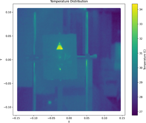
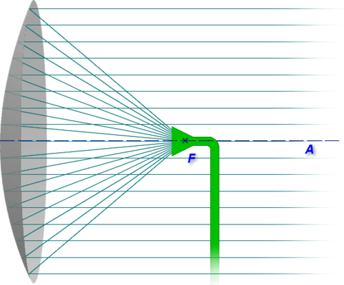
I also think that problem is not in the focal point of the reflector because we can see very well in the center of the screen, but maybe it is because in the parabolic reflector the reflection in the focal point is "extremely" straight, so for you to see the reflection in this point you need keep close to the middle of the screen, to see around the reflector, at the extremes, we need to change the position for the cable or the light to "change" how the flashes of light reflect and thus achieve exactly the position on the camera. It is something like the sketch/ photo attached below. |
| Attachment 1: AcquisitionImage(Jul-03-2023_14_29).jpg
|
.jpg.png)
|
| Attachment 2: AcquisitionImage(Jul-03-2023_14_31).jpg
|
.jpg.png)
|
| Attachment 3: AcquisitionImage(Jul-03-2023_14_49).jpg
|
.jpg.png)
|
| Attachment 4: Caderno_sem_título_(26)-2.jpg
|
-2.jpg.png)
|
| Attachment 5: parabol1.print.png
|
|
|
149
|
Thu Jul 6 18:03:19 2023 |
Pamella | Update | FLIR | FLIR project - New configuration |
[Pamella]
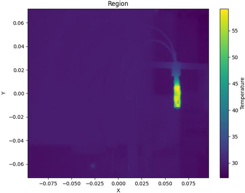
Cao suggested using the project without the reflector and mask because in this case we probably got good images around the screen. So I started this yesterday and today I started to get some data to see the stabilization position and check how the parameters fluctuated. I was looking and taking snaps for an hour and a half. I'll repeat this one more time to make sure we have enough data to do analysis.
To do: The next step is to start collecting data by moving the camera FLIR and covering all six positions on the screen (2x3). Also Aiden is on hand to help and is going to make a new 3D print bridge to have good heater support.
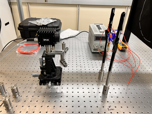
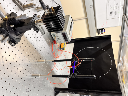
I attached a image for the new configuration below and a snap data. |
| Attachment 1: IMG_8193.jpeg
|
|
| Attachment 2: IMG_8183.jpeg
|
|
| Attachment 3: AcquisitionImage(Jul-06-2023_17_18)_(1).jpg
|
_(1).jpg.png)
|
| Attachment 4: region_temperature1.jpg
|
|
|
151
|
Sat Jul 8 14:26:17 2023 |
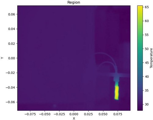
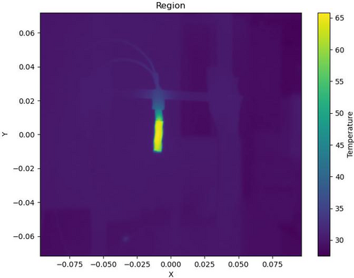
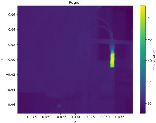
Pamella | Update | FLIR | Data with the new configuration without the mask and reflector. |
| [Pamella]
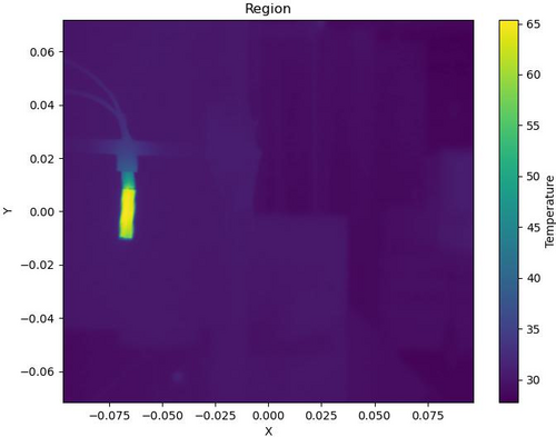
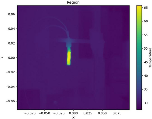
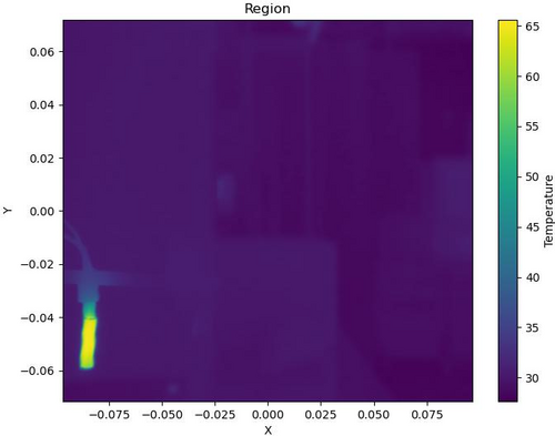
I started collecting data by moving the camera FLIR and covering all six positions on the screen (2x3). I was looking and taking snaps for more than one hour and a half. I'll repeat this one more time to make sure we have enough data to do analysis.
I attached snap data below. This images is processed on python code. |
| Attachment 1: region2-3.jpg
|
|
| Attachment 2: region3-2.jpg
|
|
| Attachment 3: region4.jpg
|
|
| Attachment 4: region5.jpg
|
|
| Attachment 5: region6.jpg
|
|
| Attachment 6: region_temperature1-2.jpg
|
|
|
157
|
Fri Jul 14 16:49:42 2023 |
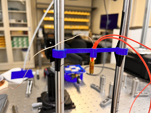
Pamella | Update | FLIR | New bridge and calibration data |
[Pamella]
Aiden 3D printed a new bridge for the heater and I installed the new bridge yesterday.
I started collecting data to plot a calibration with the heater. I'm doing measurements with current and the thermocouple (thermometer) to compare with FLIR measurements and have a good calibration. |
| Attachment 1: IMG_8606.jpeg
|
|
|
159
|
Mon Jul 17 11:46:24 2023 |
Pamella | Update | FLIR | Thermocouple plot. |
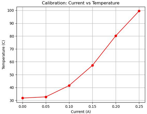
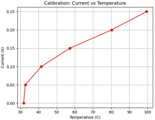
[Pamella]
- I collected data to plot a calibration with the heater. I took measurements with current and temperature (the thermocouple - thermometer) to compare with the FLIR measurements.
- I made a plot with this data and we can see how temperature vs current behaves.
Note: This data I measured manually.
|
| Attachment 1: calibration_plot-2.jpeg
|
|
| Attachment 2: calibration_plot-3.jpeg
|
|
|
163
|
Tue Jul 18 16:04:26 2023 |
Pamella | Update | FLIR | Setup FLIR with black wall (black body) |
[Pamella]
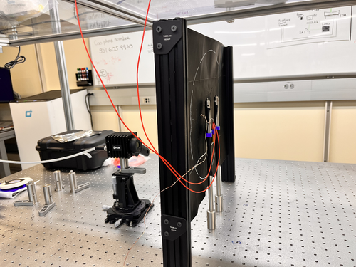
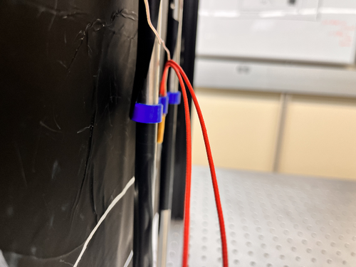
- Today I tried get data the heater with the black screen but doesn't looks possible have just one "energy" point straight to FLIR camera. Tyler and I tried different current and temperatures but keep very bad data. I attached a snap below.
- I attached a photo about the new setup below. The FLIR is in the most close point possible/safety with the heater. The heater is very close to the black wall but is not touch the screen so is safety.
|
| Attachment 1: AcquisitionImage(Jul-18-2023_15_24).jpg
|
.jpg.png)
|
| Attachment 2: IMG_8721.jpeg
|
|
| Attachment 3: IMG_8722.jpeg
|
|
|
164
|
Tue Jul 18 16:12:27 2023 |
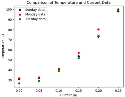
Pamella | Update | FLIR | Thermocouple plot. |
- I noticed that these measurements have some issues with the weather on different days. We can see in the photo attached below how different the temperatures are on different days, I took the data with the same procedure every day, but we can see the differences between them.
- To Do: I will do a new data collection using FLIR and thermocouple at the same time to plot comparison between both.
| Quote: |
[Pamella]
- I collected data to plot a calibration with the heater. I took measurements with current and temperature (the thermocouple - thermometer) to compare with the FLIR measurements.
- I made a plot with this data and we can see how temperature vs current behaves.
Note: This data I measured manually.
|
|
| Attachment 1: Comp.plot.jpeg
|
|
|
165
|
Tue Jul 18 16:35:06 2023 |
Pamella | Update | FLIR | Plot-Data with the new configuration without the mask and reflector. |
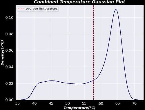
[Pamella]
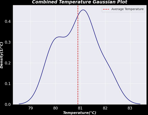
- I was able to plot the first graph for a result between the six different positions on the screen, for now we can see the behavior of the heater temperature in a Gaussian graph with combination data between the six files.
- To do: Tyler gave me some ideas today to improve the plot. So I'm going to change the code to have insulation on the values for just the heater ("insulation") and I'm going to plot after this insulation data as well I'm going to get more data and compare with more data for the same position.
- I was using the data than I got last week and I shared on Elog (151) and we can see on this quote
| Quote: |
| [Pamella]
I started collecting data by moving the camera FLIR and covering all six positions on the screen (2x3). I was looking and taking snaps for more than one hour and a half. I'll repeat this one more time to make sure we have enough data to do analysis.
I attached snap data below. This images is processed on python code. |
|
| Attachment 1: Gauss.plot.jpeg
|
|
|
167
|
Wed Jul 19 19:10:31 2023 |
Pamella | Update | FLIR | Data plot FLIR and updates. |
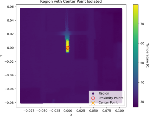
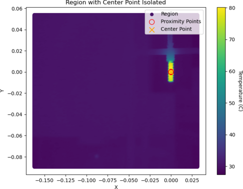
[Pamella]
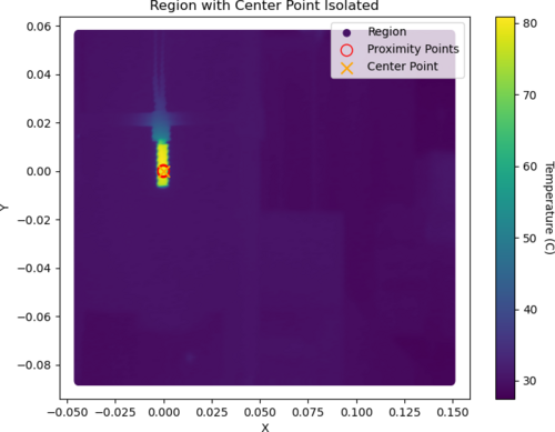
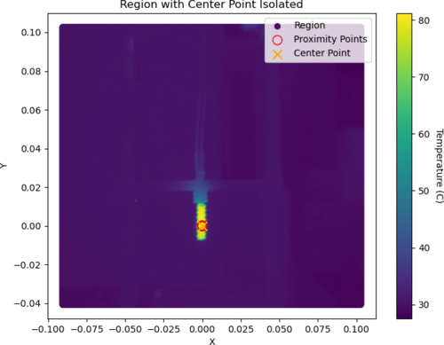
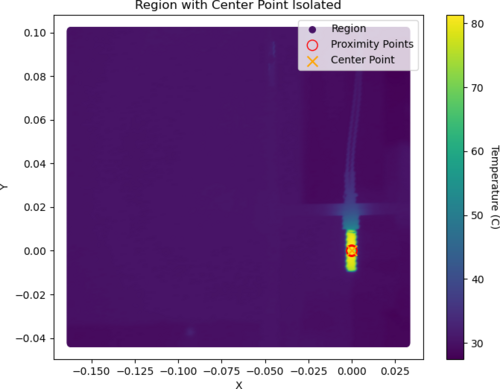
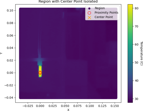
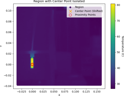
- Today I was able to plot a graph for the isolation point on the center of the heater. I got data from six different positions on the screen (I shifted the all coordinates). I extracted the data for the center point and plot the Gaussian with this extracted data for temperature. I attached the all plots below
- Also I took a snap using the black wall and with the heater at 120.1 C (0.30 A) try to have less noise but
we can see this is not very good. At this temperature, we have noise on the top and I don't understand why because the heater is not in this location. I attached a snap below.
|
| Attachment 1: 1_Isolated_Plot.png
|
|
| Attachment 2: 2_Isolated_Plot.png
|
|
| Attachment 3: 3_Isolated_Plot.png
|
|
| Attachment 4: 4_Isolated_Plot.png
|
|
| Attachment 5: 5_Isolated_Plot.png
|
|
| Attachment 6: 6_Isolated_Plot.png
|
|
| Attachment 7: Gauss.plot-2.jpeg
|
|
| Attachment 8: AcquisitionImage(Jul-19-2023_17_01).jpg
|
.jpg.png)
|
|
169
|
Thu Jul 20 21:00:23 2023 |
Pamella | Update | FLIR | Data plot FLIR and updates about the black body |
[Pamella]
- Today I got more data to plot the Gaussian. So I took more snaps in each position for the six different spots than we be using to have a better calibration of the FLIR collected data. I attached the new plot below. Also, I did the same plot for each region as on the Elog 167 but I have more than 20 pics because I was using a big number of data so I just attached one example below.
To access the Elog, click here.
- Also I think we have some real (non-ideal) heat diffusion by the screen and not noise like Dr. Richardson suggested. I was testing today and we can see the first pic before the start heater source turns on, the second pic is at 120.2 C (0.31A) with the heater on and the last pic is after the heater source cooled back down to room temperature. Just in the second pic, we have a strong spot on the top, so it looks like a non-ideal diffusion.
|
| Attachment 1: AcquisitionImage(Jul-20-2023_13_09).jpg
|
.jpg.png)
|
| Attachment 2: AcquisitionImage(Jul-20-2023_13_15).jpg
|
.jpg.png)
|
| Attachment 3: AcquisitionImage(Jul-20-2023_13_33).jpg
|
.jpg.png)
|
| Attachment 4: AcquisitionData-480(Jul-20-2023_SIsolated_Plot.png
|
|
| Attachment 5: Gauss.plot-2.jpeg
|

|
|
181
|
Fri Jul 28 18:03:07 2023 |
Pamella | Update | FLIR | Final plot - FLIR |
[Pamella]
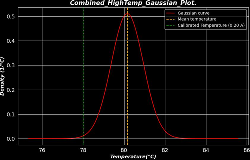
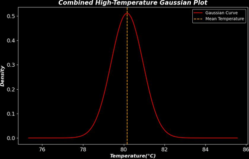
- I was able to plot the final result with the data to the heater. I attached below the "3Combined_HighTemp_Gaussian_Plot." in this plot we can see better behavior on the Gaussian compared to the plot in ELOG 169, I was using the same data but with a different approach. On the ELOG 169, we have the center point isolated data and this new plot is the temperature more than 70 C isolated because we have a very good heater temperature distinguish do background. For the all data I got I was using a power current of 0.20A. To get the data I waited for 30 minutes until the heater became stable and after that, I started to take snaps, I took more than one snap for each one different 6 positions on the screen, and We can see the positions on ELOG 167.
- Also I attached the calibration plot ("calibration_plot") between the measurements with the FLIR camera and thermocouple and we can see looks good if we compare the final plot.
- For better analyses I attached a plot of the calibration line on the Gaussian plot.
- To do: I will finish the final report.
|
| Attachment 1: 29Combined_HighTemp_Gaussian_Plot.jpg
|
|
| Attachment 2: 3Combined_HighTemp_Gaussian_Plot.jpg
|
|
| Attachment 3: calibration_plot(2).png
|
.png.png)
|
|
323
|
Tue Feb 13 11:54:45 2024 |
Tyler | Configuration | FLIR | In-Air Optical Test Configuration |
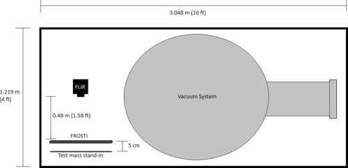
Below is the proposed schematic for FROSTI optical testing, chosen so enough space is allotted for prototype assembly.
Steps to be taken include:
- Reconstruct FLIR staging apparatus
- Move test mass stand-in to cleanroom
- Mark FLIR camera position on cleanroom optical table at correct distance
- Run ethernet cable into cleanroom
- Move FLIR aside to allow for more assembly space
- Upon assembly completion, reposition FLIR onto optical table again
Tentative plan is to begin setup early next week. |
| Attachment 1: In-air_optical_test_sketch.png
|
|
|
338
|
Fri Feb 23 18:03:27 2024 |
Tyler | Update | FLIR | Optical Test Setup in Cleanroom |
| [Tyler, Xuesi]
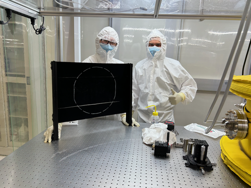
The FLIR and test mass stand-in have been transferred into the cleanroom. A software test will be run as soon as we get an ethernet cable long enough to reach into the cleanroom where the camera is set up. Once this is finished, the FLIR will be moved aside for construction of the FROSTI! When completed, the camera will be placed back into position for in-air optical testing.
|
| Attachment 1: IMG_0941.png
|
|
|
349
|
Tue Mar 19 10:55:30 2024 |
Tyler | Update | FLIR | In-Air Optical Test |
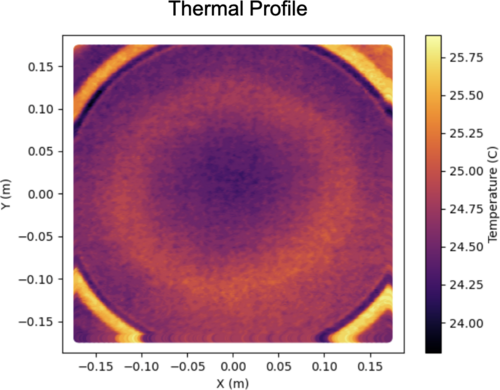
| Below is an image I took using the FLIR just before leaving for the LVK meeting. The profile is roughly what we would expect (annular). Any distortions seen are likely from the screen not being completely parallel to the plane of the FroSTI (i.e. the screen slightly bends in various locations). Next step: In-vacuum test at CIT. |
| Attachment 1: FroSTI_Thermal_Profile.png
|
|
|
366
|
Mon May 13 13:03:41 2024 |
Tyler | Update | FLIR | Readout Code Updates |
| [Tyler]
Some changes have been made to the FLIR readout code to help improve its functionality:
- More accurate temperature readings than before due to updates in the calculation procedure. A bug was causing one of the parameters to not update correctly; this is now fixed.
- Saved data now stored in HDF5 files rather than CSV.
- User can now enable automatic data storage by specifying a collection interval (in minutes). The choice of manually saving data is still present if desired.
Below is an image of the graphical interface. This is an old screenshot. Visually, there is no difference between the older and newer version. The differences come from the list above, which help the user more reliably measure and store data for later analysis.
|
| Attachment 1: AcquisitionImage(Jul-18-2023_15_24).jpg.png
|
.jpg.png.png)
|
|
373
|
Mon Jun 3 14:14:39 2024 |
Tyler | Update | FLIR | Initial CIT FROSTI Analysis |
| [Tyler]
Attached below are the initial results of the CIT FROSTI testing analysis.
|
| Attachment 1: CIT_FROSTI_Analysis_Group_Meeting-2.pdf
|

|
|
375
|
Mon Jun 10 14:52:38 2024 |
Tyler | Update | FLIR | CIT FROSTI Analysis Update |
| [Tyler]
Upon further inspection, one adjustment was made to the FROSTI profile analysis: changing the transmission value of the ZnSe viewport. It was initially assumed that the viewport possessed an AR coating, which would bring the transmission into the 90% range. Without the coating, it drops to roughly 70%. Assuming no coating, the estimated delivered power was calculated to be 11.7 W. This is consistent with the estimated power given from the Hartmann sensor analysis, thus it is believed that the viewport indeed had no coating.
| Quote: |
| [Tyler]
Attached below are the initial results of the CIT FROSTI testing analysis.
|
|
| Attachment 1: FROSTI_HR_Temperature_Difference-7.png
|

|
|
396
|
Mon Jul 8 10:39:14 2024 |
Xuejun | Update | FLIR | Average Temperature Profile |
After taking data for each of the individual heater elements, I imported them into python and overlayed them to produce an average temperature profile. I rotated the 7 of the elements to align with element 1's profile and averaged them out. By setting the range to 28C - 33C (this gave the best visibility of the heating pattern) it gave the profile attached. |
| Attachment 1: Average-Temperature-Profile.pdf
|

|
|
552
|
Tue Apr 15 11:09:37 2025 |
Liu | Update | FLIR | Test Mass Thermal State Decoder Update with robustness study |
|
| Attachment 1: Update.pdf
|

|
| Attachment 2: Update.pdf
|

|
|
14
|
Wed Dec 14 18:34:33 2022 |
Jon | Configuration | Electronics | Adapter for 532 nm laser power supply |
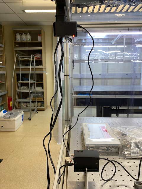
| I installed an EU-to-US plug adapter for the 532nm laser's 9V power supply. I then re-measured the laser's power with the correct supply voltage (previously we had been using a 6V supply). At 9V, the max power is 0.83 W, so the laser is confirmed to be Class 2 as labeled. |
| Attachment 1: laser_power.png
|
|
|
128
|
Tue Jun 20 17:28:23 2023 |
Pamella | Update | Electronics | Heater system parts - Wiped |
[Pamella]
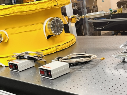
Wiping the heater system parts.
- 04:37 pm: Started wiping the electronic device part for the heater system (HL101 Series Digital Benchtop temperature limit control).
- 05:19 pm: Finished wiping the parts to the heater system (HL101 Series Digital Benchtop temperature limit control). I wiped the HL101 Series Digital Benchtop temperature limit control and I didn't bagged and tagged because we should install that soon.
- 05:23 pm: I putted heater electronic device inside the cleanroom without the bag. Also the electronic device is near to the vacuum chamber and the other parts to heater system.
- I attached the photo below.
|
| Attachment 1: IMG_7696.jpg
|
|
|
171
|
Mon Jul 24 16:19:29 2023 |
Shane, Jon | Update | Electronics | Chassis semi-assembled and moved |
| Began assembly on AA and AI chassis today, moved them both to top work bench shelf (image attached). They are delicate so please do not disturb them or put anything on top of them. |
| Attachment 1: IMG_8386.pdf
|

|
|
172
|
Tue Jul 25 15:35:14 2023 |
Shane | Update | Electronics | More chassis moved |
| Finished basic assembly of binary input and output chassis today, and moved one to top shelf of work bench. The other is in corner of work bench (image attached). They are delicate, so please do not move them or place anything on top of them. |
| Attachment 1: IMG_8409.HEIC
|
|
176
|
Thu Jul 27 14:46:55 2023 |
Shane, Jon | Update | Electronics | AA chassis DC on/off switch assembled |
| Made the first DC on/off switch assembly today and installed in anti-aliasing chassis. Second switch assembly to be completed later. |
|
182
|
Mon Jul 31 12:39:01 2023 |
Shane | Update | Electronics | LED cable assemblies installed |
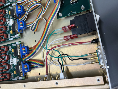
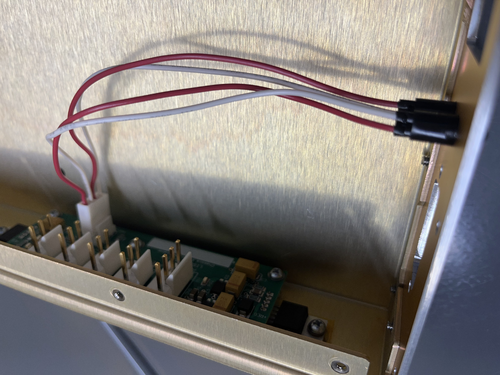
| Today I put together the two LED cable assemblies for the CyMAC and mounted them in the anti-aliasing and anti-imaging chassis. |
| Attachment 1: IMG_8514.jpeg
|
|
| Attachment 2: IMG_8516.jpeg
|
|