| ID |
Date |
Author |
Type |
Category |
Subject |
|
51
|
Tue Mar 14 18:21:41 2023 |
Aiden | Summary | General | Clean and Bake batch 8 |
| Starting off Peter and I refilled the deionized water barrel.
Then Aiden Cleaned and Bake the FROSTI arms and bases in liquinox for 5 minutes. Then placed them in the oven where they will undergo the following steps;
1. Ramp to 100 degC in 15 min.
2. Dwell at 100 degC for 30 min.
3. Ramp to 120 degC in 30 min.
4. Dwell at 120 degC for 48 hours.
5. OFF
Also cleaned the 2.75 MDC Gate valve for 20 minutes (10 minutes each side) in liquinox. It looks significantly cleaner in areas I could not reach before. However some areas like the flat bottom threaded holes are still very dirty. I also made sure to dry it thoroughly and wrapped it in UHV foil until I further cleaning is decided. |
|
52
|
Fri Mar 17 19:46:39 2023 |
Aiden | Summary | General | Clean and Bake batch 9 |
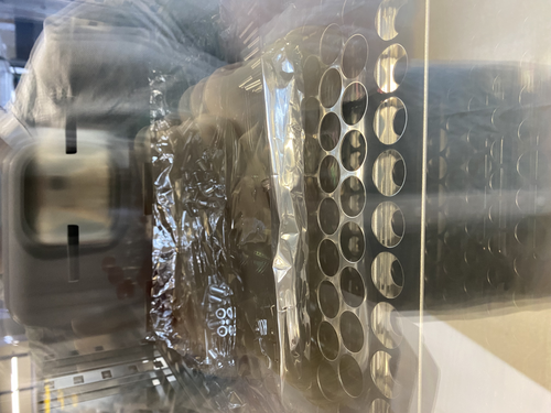
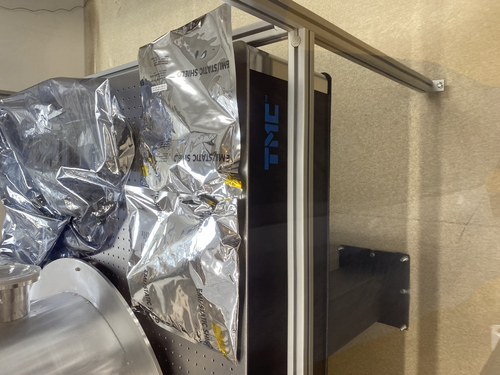
| Bagged and Tagged the reflector arms and bases and placed them inside the clean room. Total of 2 bags used. Cleaned and Baked parts in batch 9 on the spread sheet and used the following procedure;
1. Ramp to 100 degC in 15 min.
2. Dwell at 100 degC for 30 min.
3. Ramp to 200 degC in 30 min.
4. Dwell at 200 degC for 48 hours.
5. OFF
Also soaked the 2.75" CF gate valve in acetone to try and clean the open threads around the part. Then cleaned it in the ultrasonic washer with liquinox for 20 minutes (10 minutes each side). It looks better than it used to but the threads still seem to be the problem and will probably need even further cleaning. |
| Attachment 1: IMG-4208.jpg
|
|
| Attachment 2: IMG-4209.jpg
|
|
|
54
|
Wed Mar 22 15:25:00 2023 |
Shane | Update | General | Clean room recertification particle counts |
| Attached are the five zone particle measurements for the clean room now that the fan speeds have been set to MEDIUM. 2 min sample time, 3 samples per zone. The occupied clean room measurements were unusual in that they generally got larger towards minute 6 instead of settling and going to zero, and for this reason didn't stay beneath the class 5 requirement at the end of the samples. The unoccupied counts look more similar to what was expected, and generally settle under the class five requirement. |
| Attachment 1: counts3.22.23.pdf
|

|
|
55
|
Thu Mar 23 18:40:08 2023 |
Julian | Update | General | Cleanroom Update |
| Today Pamella and I came in to Hepa vacuum and mop the floor of the cleanroom for general maintenance. |
|
57
|
Fri Mar 24 13:36:17 2023 |
Pamella | Update | General | Clean and Bake batch 10 |
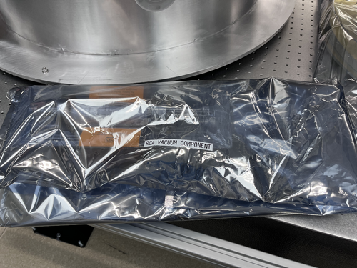
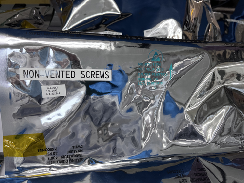
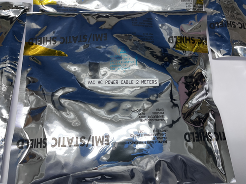
| Today I bagged and tagged batch 10.
I wiped the RGA vacuum component for around 25 minutes after that I bagged and tagged this part and put inside the cleanroom. The RGA vacuum component have a big size and because off that i used the big bag.
I wiped one power cable (2 meters), bagged and tagged that and inside the cleanroom.
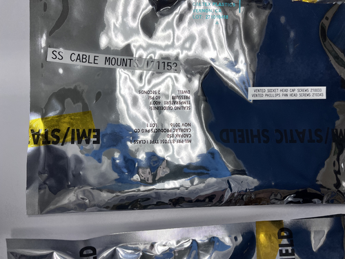
For the parts in the oven, a bunch of screws, I bagged and tagged the screws and put inside the cleanroom.
I put photos below about this process. |
| Attachment 1: 260AEB73-02D0-4635-93B3-B2EB3269FB84.jpeg
|
|
| Attachment 2: 59FD199A-A444-439A-8D51-C242B65BBECD.jpeg
|
|
| Attachment 3: 9A48A0EE-5EFE-409D-ACC0-17011F6F7EBF.jpeg
|
|
| Attachment 4: 950F85B7-D304-4724-AB3D-B606E422F1E3.jpeg
|
|
|
59
|
Fri Mar 31 14:23:13 2023 |
Pamella | Update | General | Clean and bake batch 11 |
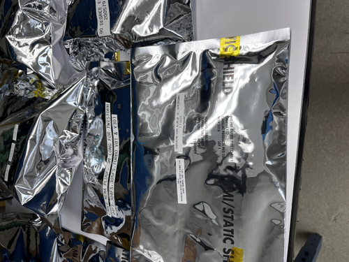
| Today I bagged and tagged batch 11. I wiped the some tools: Centering ring alum( 2 pieces), reversible ratcheting, gasket removal (CF). After wiped that I bagged and tagged this parts and put inside the cleanroom.
Also I wiped one power cable (3 meters), bagged and tagged that and inside the cleanroom.
I put photo below. |
| Attachment 1: 4AC705B8-D906-47E3-86E4-49E4967910E7.jpeg
|
|
|
60
|
Mon Apr 3 17:04:05 2023 |
Aiden | Summary | General | IDP Scroll Pump Assembly |
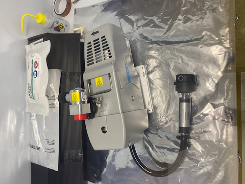
| Aiden installed the isolation valve and the exhaust silencer kits on the IDP-3 Scroll pump. The entire assembly still needs to be wiped down but overall no residue came off when putting on the kits. |
| Attachment 1: IMG_4244.jpg
|
|
|
66
|
Fri Apr 7 09:48:09 2023 |
Pamella | Update | General | Clean the system parts |
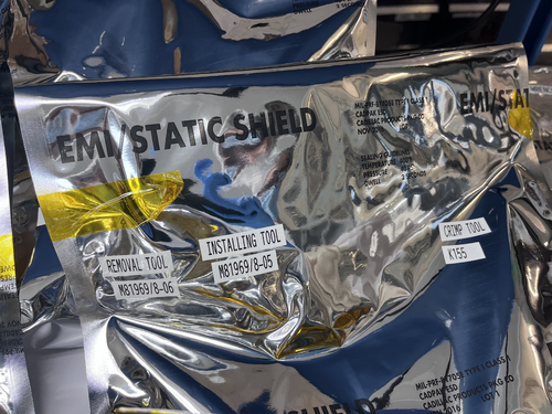
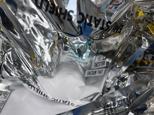
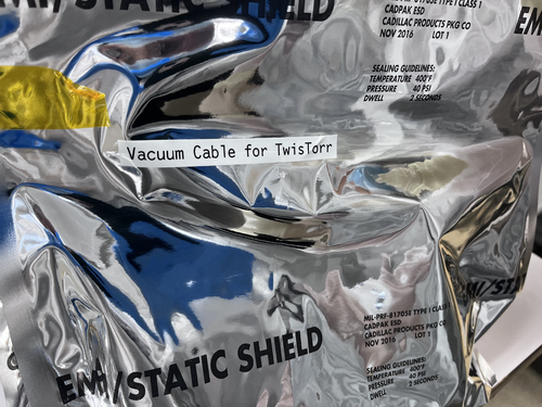
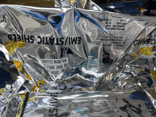
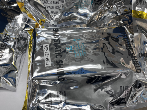
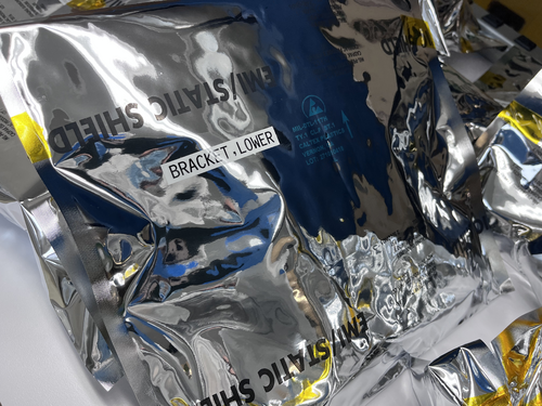
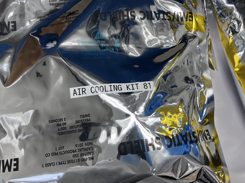
| Pamella and Julian wiped and tag system parts for the vacuum machine. We used isopropyl and vectra wipes in the most import pieces:
Inverted magnetron pirani gauge and the air cooling kit 81. The other parts we uses the IPA wipe for cleaning.
So for now we finished with ever system parts which was in the gabinetes.
I put photos below. The photos is for all part we cleaning, tag and which puted inside the cleaning room. |
| Attachment 1: 645E597D-AEA6-4669-B967-08C82AA84D13.jpeg
|
|
| Attachment 2: 2669F0AC-69BC-422B-8723-AD047F3EBEB6.jpeg
|
|
| Attachment 3: 7731FE17-EDD2-46B4-B6E1-546531D98EC3.jpeg
|
|
| Attachment 4: F8921950-63C3-4E03-B79E-0A4C8EDB8EF6.jpeg
|
|
| Attachment 5: AA9374DB-377C-48BD-866B-D686AF945D09.jpeg
|
|
| Attachment 6: B3CE9D1E-A01E-4747-9F01-D427097F340C.jpeg
|
|
| Attachment 7: BAE63151-D3D1-41D9-881E-B6175544811C.jpeg
|
|
|
68
|
Tue Apr 11 17:56:15 2023 |
Pamella | Update | General | Lab cleaning |
| Today Pamella and Julian finished cleaning of the cleanroom, starting with the HEPA vacuuming, mopping and clearing all floor with IPA wipes. Also we wiped down some surfaces of the blue table, computer table and the top of chamber. |
|
69
|
Wed Apr 12 10:53:02 2023 |
Aiden | Summary | General | Valve Cleaning |
| Bagged and Tagged the parts from batch 10 and placed them inside the clean room.
Then cleaned the last gate valve in liquinox for 20 minutes (10 minutes each side). Then dried the valve, bagged, tagged, and placed it inside the clean room. |
|
71
|
Wed Apr 12 16:17:50 2023 |
shane | Update | General | Particle Counter moved |
| With the added height of the new docking station, the particle counter no longer fits under the Windows monitor in the electronics rack and has been moved to the desk in the corner of the lab. |
| Attachment 1: IMG_6693.HEIC
|
|
72
|
Mon Apr 17 17:06:49 2023 |
Aiden | Summary | General | Clean and Bake batch 11 |
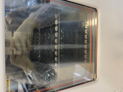
| Cleaned the Viton O-Ring for the main chamber in Liquinox for 10 minutes. Then put it in the oven to back for;
1. Ramp to 100 degC in 15 min.
2. Dwell at 100 degC for 30 min.
3. Ramp to 180 degC in 30 min.
4. Dwell at 180 degC for 24 hours.
5. Off
Note: There were three viton -rings in the bag sent to us. I cleaned and baked 2 of them and left the third in the bag. |
| Attachment 1: IMG_4262.jpg
|
|
|
76
|
Fri Apr 21 16:51:26 2023 |
Pamella | Update | General | Cleaning cables. |
Cables for the vacuum system.
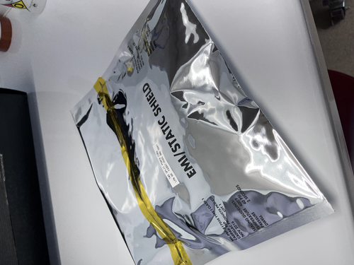
- Today i wiped, bagged and tagged two cables for the vacuum system. I used IPA wipes for cleaning this two split power cord. I attached a image below.
|
| Attachment 1: IMG_5416.jpeg
|
|
|
77
|
Mon Apr 24 17:38:45 2023 |
Aiden | Summary | General | Clean and Bake Batch 12 |
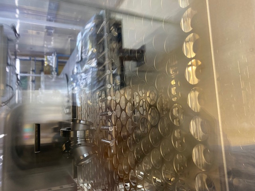
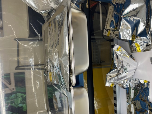
| Today I Bagged and tagged the o-rings from batch 11 and placed them inside the clean room. I also cleaned batch 12 parts in liquinox for 10 minutes and them placed them into the oven where they will undergo the following steps;
1. Ramp to 100 degC in 15 min.
2. Dwell at 100 degC for 30 min.
3. Ramp to 200 deg C in 30 min.
4. Dwell at 200 deg C for 48 hours.
5. Off |
| Attachment 1: IMG_4269.jpg
|
|
| Attachment 2: IMG_4268.jpg
|
|
|
80
|
Thu Apr 27 09:48:34 2023 |
Aiden | Summary | General | Batch 12 Bagging |
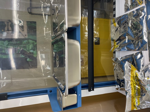
| I took batch 12 out of the oven and put them in a bag and placed the bag inside the clean room in the first large stainless steel container.
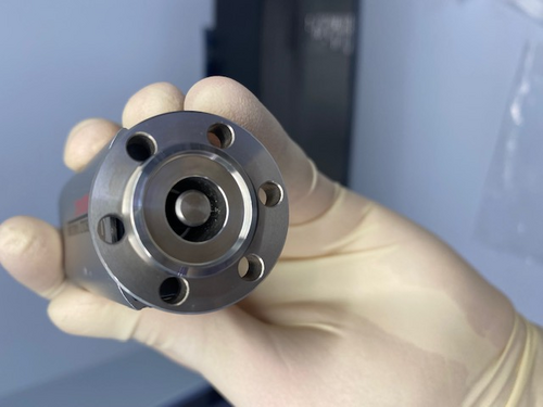
I also looked at the small gauge that we felt like needed to be baked and I can confirm that without further cleaning around the inside of the gauge it should not be connected to the main vacuum. I have attached a photo of the inside of the gauge. |
| Attachment 1: IMG_4279.jpg
|
|
| Attachment 2: IMG_4278.jpg
|
|
|
86
|
Fri Apr 28 19:39:19 2023 |
Cao | Summary | General | Clean and Bake Leybold TTR 91 Pirani Gauge |
| Quote: |
| I took batch 12 out of the oven and put them in a bag and placed the bag inside the clean room in the first large stainless steel container.
I also looked at the small gauge that we felt like needed to be baked and I can confirm that without further cleaning around the inside of the gauge it should not be connected to the main vacuum. I have attached a photo of the inside of the gauge. |
Following the problem with contamination particles observed in the the Leybold thermovac TTR 91, we have taken the following step to clean the gauge:
- Wipe with IPA-wetted Vectra Alpha: Cover the tip of a ziptide with Vectra Alpha wipe corner that has been wetted with IPA, push the wipe around and remove visible particulates
- Fill the gauge flange with IPA: (following Jon's recommendation to use Lesker's procedure for cleaning their Pirani gauge), flip the gauge up such that the CF flange points upward, fill the flange with IPA all the way up. Use the tip of a SSTL tweezer to agitate the IPA. Let it sits for 20 minutes, agitate every 5 minutes. After 20 minutes, pour the IPA out then spray with dry pure nitrogen
- Passive drying : Let the gauge sit inside the flowbench for 3 hours (3:30 pm to 6:30 pm)to ensure all IPA has evaporated
- Baking : Leave the gauge in oven at 50 degree C for 48 hours (maximum allowed temperature is 65 deg C, we use 50 deg C to ensure we are well below this limit). Baking started at 7pm, should finish on Sunday 7pm and ready for assembling to vacuum chamber on Monday morning
|
|
93
|
Mon May 8 12:00:03 2023 |
Pamella, Shane, Julian | Update | General | Cleanroom particle counts and cleaning the cleanroom. |
[Pamella,Julian, Shane]
Today we cleaned the clean-room (floor, surfaces) and particle count.
10:00 am: Started particle count.
- Zone 3:
- 0.3u: 1330
- 0.5u: 540
- 1.0u: 415
- Zone 4:
- 0.3u: 290
- 0.5u: 83
- 1.0u: 0
Clean-room:
- 10:30 am: Started wiping down the surfaces inside the clean-room
- 10:41 am: Finished wiping down the surfaces inside the clean-room and Started vacuuming the clean-room.
- 10:58 am: Finished vacuuming the clean-room.
- 11:00 am: Started mopping on the floor.
- 11:20 am: Finished mopping on the floor and started wiping on the floor.
- 11:34 am: Finished wiping on the floor.
- 11:35 am: Started the particle count.
- 11:57 am: Finished the particle count.
- Zone 3
- 0.3u: 997
- 0.5u: 290
- 1.0u: 207
- Zone 4
- 0.3u: 374
- 0.5u: 207
- 1.0u: 207
|
|
96
|
Wed May 10 10:49:34 2023 |
Aiden | Update | General | RGA Software |
| [Aiden, Cao]
Went over how to use the RGA software, how to change the graph units, scaling and mass detection. Also went over how to remove the RGA from the vacuum system as well as procedure for turning it on. |
|
100
|
Wed May 17 12:18:08 2023 |
Pamella, Julian and Shane | Update | General | Cleaning room and particle count |
[Pamella, Julian and Shane]
Particle count:
- 10 am: Started particle count
- Zone 3 :
- 0.3u: 1288
- 0.5u: 332
- 1.0u: 124
- Zone 4 :
- 0.3u: 498
- 0.5u: 166
- 1.0u: 83
- 10:40 am: Checked the surfaces inside the cleanroom.
- 10:50 am: Started vacuuming the cleanroom.
- 11:15 am: Started mopping the cleanroom.
- 11:35 am: Started wiping the cleanroom floor.
- 11:40 am: Finished cleaning the cleanroom.
- 11:41 am: Started the particle count.
- 12:17 am: Finished the particle count.
- Zone 3 :
- 0.3u: 3782
- 0.5u: 706
- 1.0u: 207
- Zone 4 :
- 0.3u: 374
- 0.5u: 83
- 1.0u: 83
|
|
109
|
Wed May 31 11:42:16 2023 |
Pamella, Julian and Shane | Update | General | Cleaning room and particle count |
[Pamella, Shane and Julian]
Cleaning room and particle count
- 09:58 am: Started the particle count
- Zone 3:
- 0.3u : 1,995
- 0.5u : 540
- 1.0u : 0
- Zone 4:
- 0.3u : 124
- 0.5u : 0
- 1.0u : 0
- 10:25 am: Started checking the surfaces inside the cleanroom.
- 10:30 am: Started vacuuming the floor.
- 10:45 am: Finished vacuuming the floor.
- 10:46 am: Started mopping the floor.
- 10:58 am: Finished mopping the floor.
- 11:00 am: Started wiping floor with polypropylene wipes.
- 11:03 am: Started and finished cleaning the mop buckets.
- 11:15 am: Finished wiping floor with polypropylene wipes.
- 11:16 am: Changed sticky floor mats.
- 11:20 am: Started the particle count.
- Zone 3:
- 0.3u : 2,951
- 0.5u : 872
- 1.0u : 207
- Zone 4:
- 0.3u : 374
- 0.5u : 83
- 1.0u : 0
|
|
111
|
Wed May 31 16:18:41 2023 |
Aiden | Summary | General | Mock FROSTI |
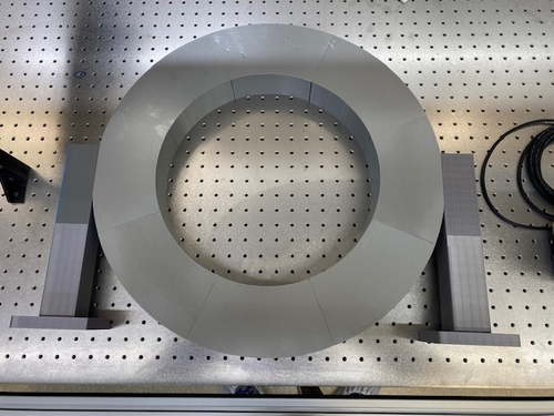
| Finished assembly on the Mock FROSTI so it is ready for the fit test at LIGO lab. |
| Attachment 1: IMG_4394.jpg
|
|
|
115
|
Tue Jun 6 16:04:46 2023 |
Aiden | Update | General | Water |
| Aiden went and refilled the de-ionized water to continue clean and bake batches. |
|
119
|
Mon Jun 12 18:52:00 2023 |
Pamella | Update | General | Heater system parts - Wiped and bagged |
[Pamella]
Cleaning the heater system parts.
- 04:32 pm: Started wiping the heater system parts.
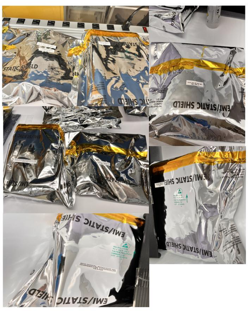
- 06:38 pm: Finished wiping the heater and some parts to the system. I wiped, tagged and bagged the heater system, power cables, adapter cables and power connectors. Also I wiped, bagged and tagged the aluminum foil tape.
- 06:43 pm: I putted all bags inside the cleanroom.
- To do: I started but I was not able to finished wiping the heating and cords for the heater system so I will finished this parts after.
- I attached the photos below.
|
| Attachment 1: heater_equipment_wiped.jpg
|
|
|
120
|
Tue Jun 13 10:28:50 2023 |
Pamella | Update | General | Wiped and bagged the heating and cords. |
[Pamella]
- Cleaning the heater system parts.
- 09:13 am: Started wiping the last parts for the heater system (heating and cords).
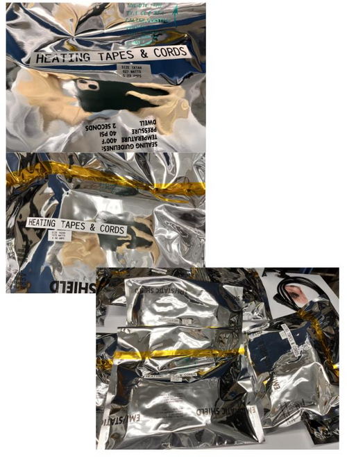
- 10:18 am: Finished wiping the parts to the heater system (heating and cords). I wiped, tagged and bagged the heating and cords.
- Note: In some parts looks like the silicone insulation material is having some sort of residue on the wipe so I wiped very careful this part and just for a few minutes.
- 10:23 am: I putted all bags inside the cleanroom.
I attached the photos below. |
| Attachment 1: heater_cords_wiped.jpg
|
|
|
123
|
Tue Jun 13 21:33:46 2023 |
Pamella | Update | General | New cabinet for PPI |
[Pamella and Dr.Richardson]
Dr. Richardson installed the new cabinet outside the room for the PPI equipments, and then I wiped all surfaces inside and outside of the new cabinet.
Dr.Richardson and I have finished organizing the PPI within the new cabinet. Also we have new supplies of gloves, and will likely have more supplies for other PPIs soon. |
|
154
|
Thu Jul 13 15:31:21 2023 |
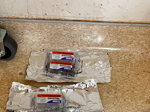
Jon | Update | General | Ant traps placed around lab |
In response to reports that ants have been observed in the lab, I placed five ant bait traps around the room today. Each is sitting on the floor on top of a piece of aluminum foil, in areas unlikely to be inadvertently stepped on. They contain liquid which will spill out if picked up, so please take care not to disturb them. |
|
155
|
Thu Jul 13 16:59:03 2023 |
Jon | Update | General | Ant traps placed around lab |
Update: After seeing the strong response to the first set, I redistributed them to the hottest spots and added one more trap.
| Quote: |
|
In response to reports that ants have been observed in the lab, I placed five ant bait traps around the room today. Each is sitting on the floor on top of a piece of aluminum foil, in areas unlikely to be inadvertently stepped on. They contain liquid which will spill out if picked up, so please take care not to disturb them.
|
|
|
158
|
Sun Jul 16 15:21:56 2023 |
Pamella | Update | General | General update about some problems in the lab. |
[Pamella]
General information about the lab facility.
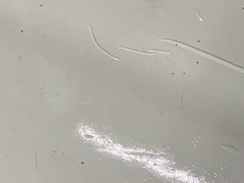
- Changed sticky floor mats, because close to entrance the cleanroom, both sticky floor had a many died ants on top.
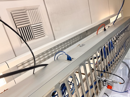
- The light on top of the internet cable bridge is burned out.. I just saw this today but I am not sure if was like this before.
- The ant bait traps seem very efficient and right now only a few ants are running around in the lab, most are dead in the bait traps, so probably in a day or two we can change those bait traps.
|
| Attachment 1: IMG_8637.jpg
|
|
| Attachment 2: IMG_8633.jpg
|
|
| Attachment 3: IMG_8631.jpg
|
|
|
198
|
Wed Aug 9 11:32:56 2023 |
Jon | Infrastructure | General | New power cables |
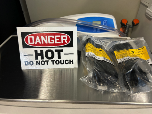
I delivered new NEMA 5-15 (120V / 15 A) power cables to the lab for the following items:
- WS2 (cleanroom) cart - 10ft cable
- Electronics workbench overhead LED - 10ft cable
- Both PI heater controller sets - (2) 6ft cables
I installed the new cables on the WS2 cart and the workbench myself, and left the two 6ft cables (as pictured below) for Aiden to install on the PID controllers after the current bake is finished. |
| Attachment 1: IMG_0299.jpg
|
|
|
217
|
Tue Aug 29 22:07:38 2023 |
Aiden | Update | General | Electronic Bench |
| Dr Richardson is working on mounting more power supplies in the server rack and is using the electronics bench. Be aware to not move anything on the bench itself. |
| Attachment 1: IMG_4632.jpg
|
|
|
220
|
Tue Sep 5 16:43:19 2023 |
Aiden | Update | General | VAC System Heating Update |
| Checked on bake 5 today after 3 days of equilibrium. The RGA cross is at 106 C and the turbo pump cross is at 74 C. This was reached while the PID controllers were at 140 C. I will now slowly raise the temperature to 150 on the PID controllers and see if the difference in the RGA cross can be reduced. |
|
257
|
Wed Nov 8 17:55:49 2023 |
Jon | Update | General | Lab Clean-Up Day 1 |
[Jon, Tyler, Shane, Peter, Luis]
Today we completed the first phase of lab clean-up. Activities included:
- CF/KF parts stored under the cleanroom table were removed and transferred to Physics 1129
- Cleanroom workbench cleared, with all FROSTI hardware collected into one of the large SS bins
- High surfaces outside the cleanroom (lights, table enclosure frames, rack, cabinets) wiped down with IPA wipes
- Floor HEPA-vacuumed outside the cleanroom
- Sticky mats changed throughout the lab
Tomorrow, we will complete turn-over of the cleanroom (HEPA vacuuming of floors, mopping of floors, IPA wiping of softwalls and work surfaces). Shane will post a forthcoming measurement of the cleanroom particulate levels, post-turnover. |
|
275
|
Tue Nov 21 22:09:44 2023 |
Aiden | Update | General | Testing Parts |
| [Aiden, Luis]
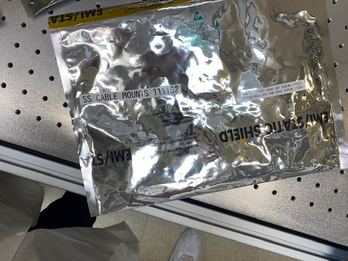
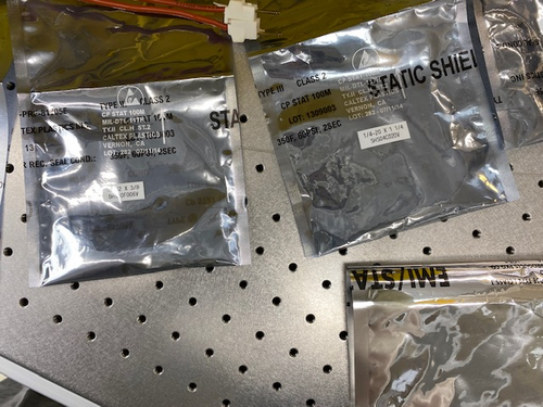
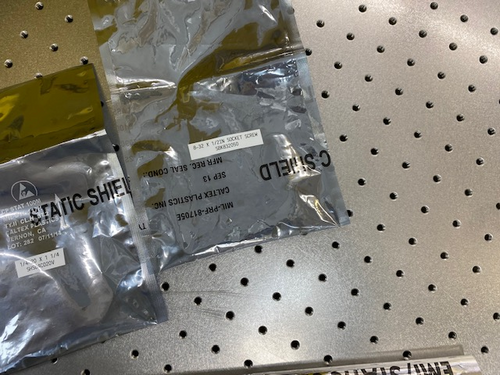
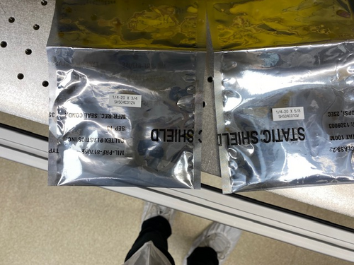
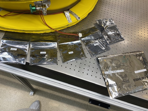
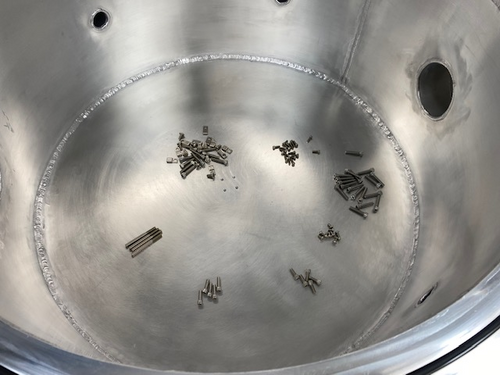
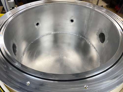
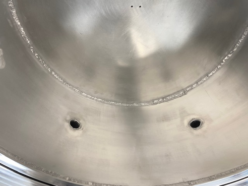
Luis and Aiden vented the chamber today. We closed off the RGA section and then proceeded to open the the vent on the main body after turning off the turbo and backing pump. We then opened the lid and placed in all the stainless steel hardware that will be used in evaluating the FROSTI optics and heater elements. We also inspected the weldments before closing it up. Check the clean and bake data base where there is now a new section outlining the parts in each test. We then closed the lid, tightened the bolts, turned the backing pump back on and let the pressure drop until it was below 1e-1 torr. Then turned the turbo pump back on and after a few hours the pressure was back down to 4.16e-7 torr. The RGA was turned off during all of this and was turned back on when done even though we closed both valves to keep the RGA volume under vacuum. |
| Attachment 1: IMG_4817.jpg
|
|
| Attachment 2: IMG_4815.jpg
|
|
| Attachment 3: IMG_4816.jpg
|
|
| Attachment 4: IMG_4814.jpg
|
|
| Attachment 5: IMG_4813.jpg
|
|
| Attachment 6: IMG_4812.jpg
|
|
| Attachment 7: IMG_4810.jpg
|
|
| Attachment 8: IMG_4811.jpg
|
|
|
289
|
Sat Dec 9 12:34:12 2023 |
Jon | Update | General | Electronics workshop migrated to 1129 |
[Jon, Tyler, Shane, Luis]
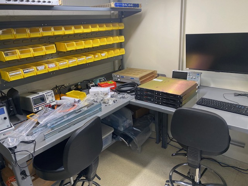
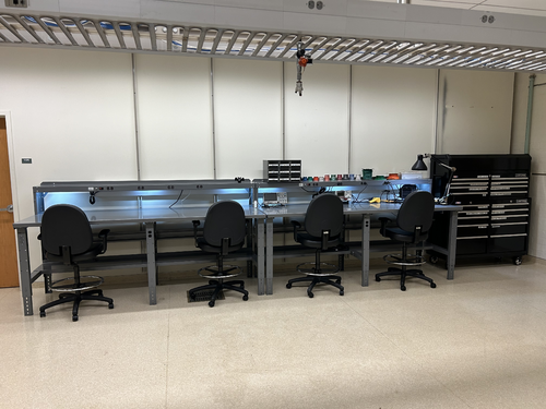
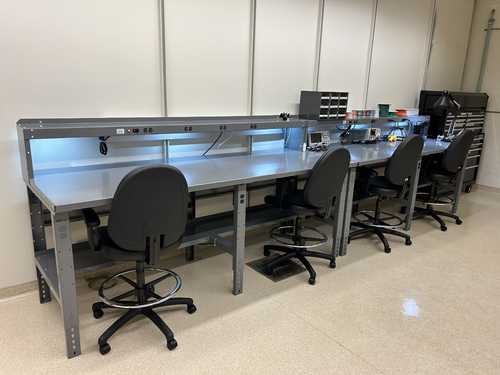
On Wednesday we completed the migration of the electronics workshop from 1119 to the large new workbenches in 1129. The two workstations pictured closest to the front of the room are for electronics assembly and testing, while the two in the rear will house LIGO CDS workstations. We moved all of the tools, cabling, and soldering and test equipment from 1119 to this new location. We also moved the large tool chest to 1129, as pictured, and moved the smaller tool chest to 1119 in its place.
The electronics workbench is ready for use. |
| Attachment 1: IMG_0765.jpg
|
|
| Attachment 2: IMG_0767.jpeg
|
|
|
299
|
Mon Jan 8 20:24:53 2024 |
Aiden | Update | General | |
| [Jon, Aiden]
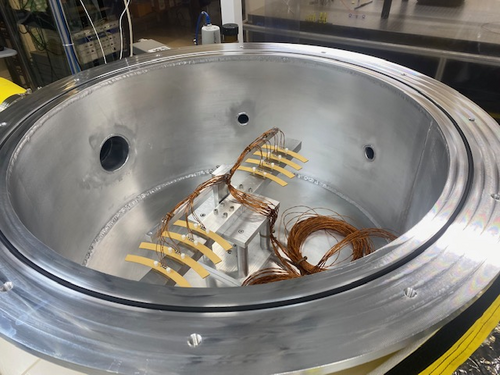
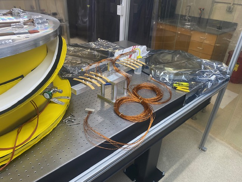
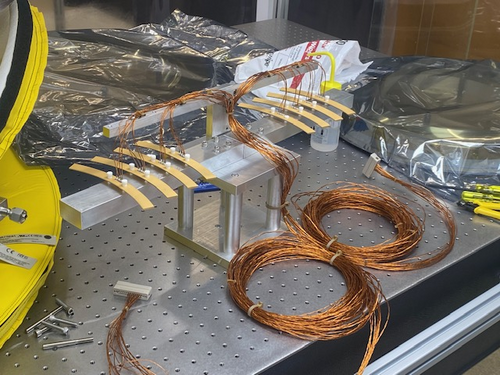
Installed the heater elements into their fixture and prepped the cables by twisting the wires into pairs. We also installed the pins onto the wires and placed them into the peek DB 25 connector. The installation tool we had did not fit the pin size we had so the pins needed to be installed by hand by opening the connector and holding them in place. In the future we will need to make sure we twist the wires together, group them, and then splice them all to the same size for easier installation. We then grouped all the twisted pairs into a bundle and zipped them together. On the left with two peek zip ties is the power and on the right is the RTD with one peek zip tie. This orientation remains true when looking at the feed through flange from the outside with the power port on closest to the wall.
We also installed the heater elements numbered 1-8 starting from the left in image 3. These elements have numbers as resistance data was taken before as to identify the heaters after they are in the chamber. After installing the DB 25 connectors we tested that the pins were in the right orientation by using a volt meter and testing the resistance where the cable runs into the the actual power supply. It seems that all the pins were properly installed and the resistance values all match with each one gaining about 2 Ohms from the cable itself.
Then the pump down was started. The pump was very slow and we suspected a leak but after changing the o-ring pump down was not any faster and we decided to leave it over break as it seemed to just be water outgassing from the aluminum. The chamber is now able to be RGA scanned and leak tested before the next bake as it is low enough pressure. |
| Attachment 1: IMG_4888.jpg
|
|
| Attachment 2: IMG_4886.jpg
|
|
| Attachment 3: IMG_4887.jpg
|
|
|
303
|
Mon Jan 15 22:29:34 2024 |
Jon | Infrastructure | General | Cabinet installation & lab clean-up completed |
[Jon, Tyler, Aiden, Shane, Pooyan, Michael, Cynthia, Luke]
On Wednesday, we completed long list of work towards making the new lab (1129) fully operational and enabling the next phase of FROSTI testing.
Cabinet Installation
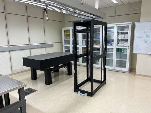
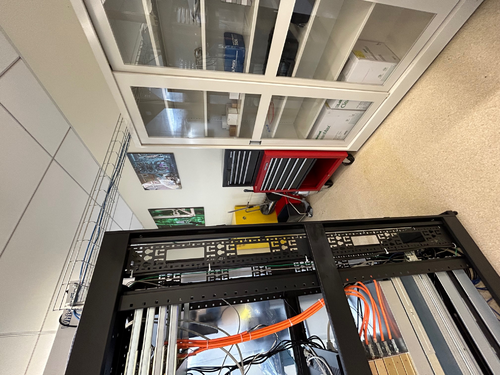
Three new VWR cabinets with sliding glass doors were installed in 1129. Each unit measures 48" (W) x 22" (D) x 84" (H) and sits along the back wall (see attachment 1). The 350-lb. cabinets were laid in place by Facilities on Monday and permanentized on Wednesday. Work included:
- Earthquake anchoring to the masonry wall
- Sliding glass doors leveled
- Shelving installed
- Wiping down of interior and exterior surfaces with IPA wipes
Server Rack Installation
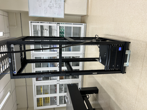
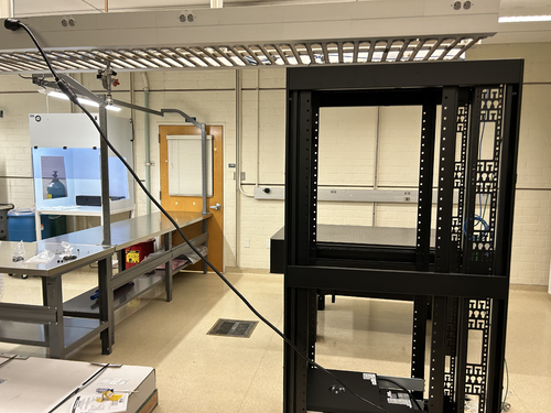
A new Tripp Lite 42U open-frame rack was laid in place in 1129 and anchored to the floor (see attachment 1). This rack will house all of our general-purpose and simulation computers, which will be relocated from the 1119 rack at a later time.
Lab Clean-Up
Following installation of the new cabinets and rack, we proceeded to organize and clean both labs. Work included:
- Moved parts and equipment into permanent storage in 1129 cabinets
- Wiped down surfaces in 1119 and 1129 with polypropylene IPA wipes
- HEPA-vacuumed floors of 1119 and 1129
- Mopped floor in 1119 with Liquinox solution
- Installed new sticky mats in 1119 and 1129
- Regular cleanroom cleaning and particle counts (see 302)
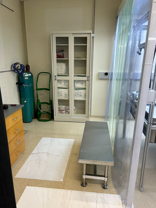
- Positioned new stainless steel gowning bench outside the cleanroom (see attachment 2)
At this point, the only piece of lab equipment still to be delivered is a HEPA garment cabinet for reusing our (semi-disposable) bunny suits. It is schedule to arrive in mid-February and will sit outside the cleanroom in 1119, in the former location of the HEPA flow bench. |
| Attachment 1: 1129.png
|
|
| Attachment 2: 1119.png
|
|
|
307
|
Wed Jan 17 15:47:49 2024 |
Aiden | Update | General | Resistors for Heater Elements |
| Power Res (Ohm) RTD Res (Ohm)
Heater 1= 73.6; 81.8
Heater 2= 70.4; 82.1
Heater 3= 71; 84.5
Heater 4= 71.5; 80
Heater 5= 70.5; 81.7
Heater 6= 72; 79.4
Heater 7= 69.2; 78.2
Heater 8= 71.1; 84.2 |
|
330
|
Tue Feb 20 08:01:30 2024 |
Jon | Infrastructure | General | Power and network equipment installed in 1129 rack |
| [Jon, Tyler, Pooyan, Luis, Luke, Peter]
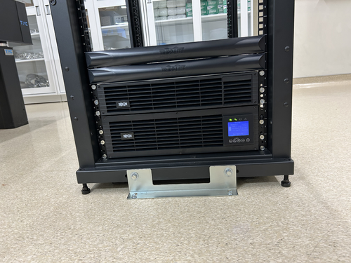
On Thursday we installed the power conditioning/distribution equipment and networking equipment in the new 1129 rack. The hardware is identical to the setup in the 1119 rack and includes:
- Tripp Lite SU5KRT3UTF - 208V, 5kVA on-line UPS with 120V transformer
- CyberPower PDU20M2F12R - metered power distribution unit, (14) NEMA 5-20R
- Ubiquiti USW-Pro-48 - 48 port 10Gbps network switch
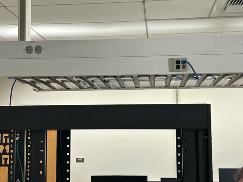
The UPS is connected to a 208V NEMA 6-30R outlet in the overhead cable tray, which is on the building's "standby" (backup power) circuit. An 8-ft L6-30 extension cord has been ordered to permanently run the power cable through the cable tray.
The network switch will be connected to a Cat6 cable that was recently run by ITS from the 1119 rack, allowing the lab's LAN to be extended into 1129. This Ethernet link remains to be tested.
| Quote: |
Server Rack Installation
A new Tripp Lite 42U open-frame rack was laid in place in 1129 and anchored to the floor (see attachment 1). This rack will house all of our general-purpose and simulation computers, which will be relocated from the 1119 rack at a later time.
|
|
| Attachment 1: IMG_0924.jpeg
|
|
| Attachment 2: IMG_0925.jpeg
|
|
| Attachment 3: IMG_0921.jpeg
|
|
| Attachment 4: IMG_0922.jpeg
|
|
|
332
|
Tue Feb 20 18:08:24 2024 |
Aiden | Update | General | Degassing the RGA |
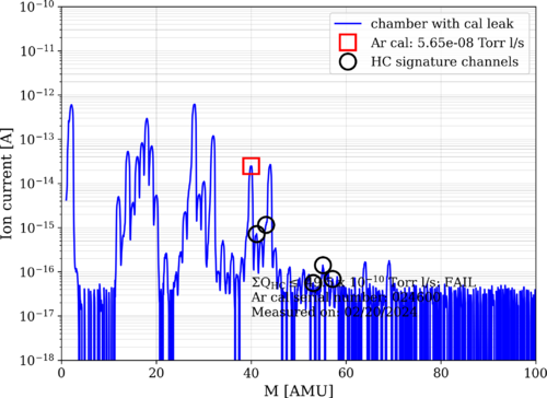
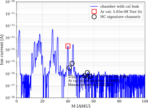
| I took an RGA measurement before and after degassing the RGA. Both data was taken with the Argon open. The pressure before taking data was 2.39 e-8 torr in the main volume. Note that the main chamber was fully valved off for the degas and the main chamber pressure quickly rose to e-6 torr. Further investigation of this rise should be done as this might be the main culprit for the leaking. |
| Attachment 1: bake11_240220_Elements_postdegas_ArO.png
|
|
| Attachment 2: bake11_240220_Elements_predegas_ArO.png
|
|
|
340
|
Mon Feb 26 15:15:39 2024 |
Aiden | Update | General | Vacuum Chamber Baking Update |
| Started Bake 12 on Wednesday Feb. 21 and turned the bake off on Saturday Feb. 24. This was a normal low temp bake with the PID controllers set to 110 degC. |
|
344
|
Wed Feb 28 12:02:08 2024 |
Tyler | Update | General | Resistors for Heater Elements Update |
| Power Res (Ohm) RTD Res (Ohm)
Heater 1= 72.8; 80.6
Heater 2= 69.5; 80.8
Heater 3= 70; 83.2
Heater 4= 70.6; 78.7
Heater 5= 69.9; 80.6
Heater 6= 71.1; 78.2
Heater 7= 68.5; 76.8
Heater 8= 70.1; 82.8
| Quote: |
| Power Res (Ohm) RTD Res (Ohm)
Heater 1= 73.6; 81.8
Heater 2= 70.4; 82.1
Heater 3= 71; 84.5
Heater 4= 71.5; 80
Heater 5= 70.5; 81.7
Heater 6= 72; 79.4
Heater 7= 69.2; 78.2
Heater 8= 71.1; 84.2 |
|
|
352
|
Sun Mar 24 11:49:27 2024 |
Aiden | Update | General | FROSTI RGA Scan |
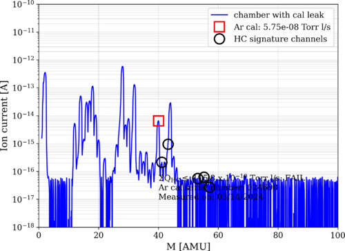
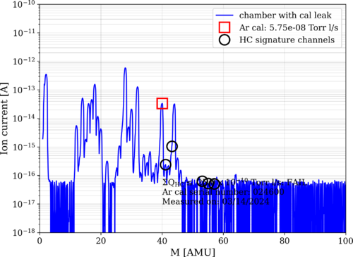
| Took RGA data 1 day after the conclusion of Bake 13. Bake 13 ended on Saturday March 23, the RGA data shown was taken on Sunday March 24. The scan shows that the FROSTI is very clean with no outgassing. The HC levels are at 25 e-10. The pressure in the chamber was also a 1.64 e-8 Torr. |
| Attachment 1: bake13_240324_FROSTI_ArC.png
|
|
| Attachment 2: bake13_240324_FROSTI_ArO.png
|
|
|
377
|
Mon Jun 17 11:47:46 2024 |
Liu | Infrastructure | General | Temporary cooling units for the labs |
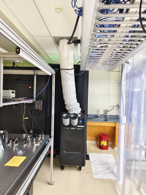
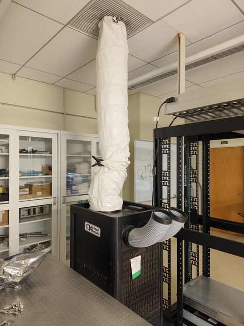
| Below are the temporary cooling units installed last week in labs 1119 and 1129. They are the temp. replacement for the building AC system, which will be shut down during the Physics roof replacement. |
| Attachment 1: 1119.jpg
|
|
| Attachment 2: 1129.jpg
|
|
|
402
|
Thu Jul 11 21:01:37 2024 |
Jon | Infrastructure | General | Cable tray installed in 1129 |
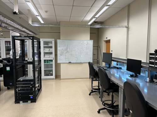
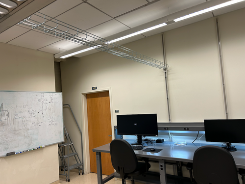
| Today I installed a 10' cable tray in 1129, for permanently routing Ethernet lines to the workstations. It is securely bolted to C-channels in the side wall and in the center cable tray. |
| Attachment 1: IMG_1395.png
|
|
| Attachment 2: IMG_1396.png
|
|
|
403
|
Sat Jul 13 15:09:04 2024 |
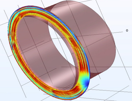
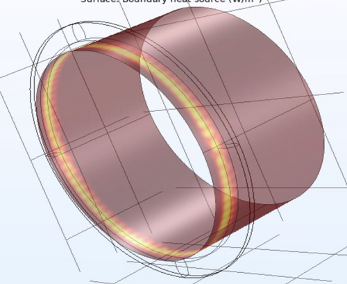
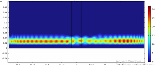
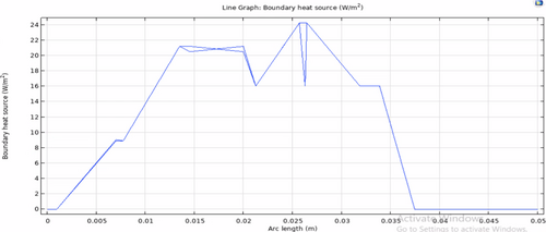
Luke | Update | General | Ring heater COMSL model update |
After the feedback from last meeting and Liu's help narrowing down what I should do to improve the model. I made some changes: First with Liu's help I made the proportions of the test mass and ring heater much more reasonable and parametrized by constants. Second from Cao's paper "FROSTI Nonimaging Reflector Design" Liu showed me what I should do to define the elliptical mirrors. Third during Friday's modeling/programming meeting walked me through getting the different irradiance plots to work. |
| Attachment 1: image_2024-07-13_150654436.png
|
|
| Attachment 2: image_2024-07-13_150704735.png
|
|
| Attachment 3: image_2024-07-13_150716079.png
|
|
| Attachment 4: image_2024-07-13_150726593.png
|
|
|
418
|
Tue Jul 30 07:42:47 2024 |
Jon | Infrastructure | General | Cable tray installed in 1119 |
| Yesterday I installed another 5' cable tray in 1119, for permanently routing Ethernet lines to the L-bench. It is securely bolted to the top of the electronics rack, on one end, and to the top of the glass-door storage cabinet, on the other. This eliminates the need for the cable ramp which previously sat behind the rack. |
| Attachment 1: cable_tray_1119.jpg
|
|
|
471
|
Wed Nov 13 14:06:00 2024 |
Luke | Update | General | |
slides |
|
483
|
Mon Dec 2 13:35:45 2024 |
Luke | Update | General | Clean and bake of Viton O-rings |
[Luke, Luis]
We couldn't access the bake log on the wiki. (see attached) So we looked in the documentation provided on the DCC to find at what temperature to bake the Viton O-rings. We found that we should bake Viton at 180°C for 24 hours.
So we sonic-washed the O-rings, dried them, and then put them in the oven set to the following:
100°C in 15 minutes
100°C for 30 minutes
180°C in 30 minutes
180°C for 24 hours
30°C in 2 hours
Other things of note:
We refilled the water container as it was running out.
The nitrogen used to dry the clean and baked objects is now critically low.
The helium used in leak testing is also quite low (~400 psi).
Regarding the vacuum chamber:
I reattached the pressure gauges to the chamber and gave them about an hour to stabilize. They read out main 8.7e-9, RGA 2.6e-9. Please note these pressures should lower more as we only stopped baking on Saturday afternoon. |
| Attachment 1: image_(2).png
|
.png.png)
|
|
500
|
Tue Jan 21 10:12:02 2025 |
Luke | Summary | General | Frosti toy model |
[Luke, Liu]
Over the winter break I have been working on this desmos toy model of the Frosti. There are still a few rough spots but I belive that it is a good visual representation of a 2D slice of the frosti. |
|
502
|
Sat Jan 25 18:19:39 2025 |
Luke | Update | General | Ringheater modeling Update |
Here is a quick update on some of the things I have been working on regarding my project. |