| ID |
Date |
Author |
Type |
Category |
Subject |
|
133
|
Tue Jun 27 12:09:37 2023 |
Shane | Update | Cleanroom | cleanroom 5 zone particle count measurement |
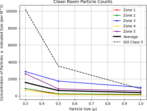
| Attached is 5 zone measurement for cleanroom particulate count. Zone 3 (in front of vacuum chamber) higher than usual, likely due to recent vac work. Slightly above ISO class 5 standard in 1.0 micron range, measuring 997 particles/cubic meter while ISO standard is 832 particles/cubic meter in this range.
Zero count test on particle counter performed prior to today's measurement. |
| Attachment 1: 23.png
|
|
|
147
|
Thu Jul 6 13:34:48 2023 |
Pamella, Shane, Julian, Aiden | Update | Cleanroom | cleaning and particle count |
|
[Pamella, Julian, Aiden, and Shane]
|
|
166
|
Wed Jul 19 14:39:19 2023 |
Pamella, Shane, Aiden | Update | Cleanroom | cleaning and particle count |
|
[Pamella, Shane, Aiden]
cleaning cleanroom and particle count
- 1:10 pm: started particle count
- 1:30 pm: began surface check and wipedown
- 1:41 pm: started vacuuming the floor
- 1:55 pm: finished vacuuming the floor
- 1:57 pm: started mopping the floor
- 2:01 pm: finished mopping the floor
- 2:02 pm: started cleaning the buckets
- 2:08 pm: started mopping with IPA wipes
- 2:17 pm: finished mopping with IPA wipes
- 2:18 pm: changed sticky floor mats
- 2:19 pm: started particle count
|
|
177
|
Fri Jul 28 13:07:39 2023 |
Shane, Aiden | Update | Cleanroom | cleanroom cleaning and particle count |
|
[Aiden, Shane]
cleaning cleanroom and particle count
- 11:08 am: started particle count
- zone 3:
- 0.3 u: 4198
- 0.5 u: 1080
- 1.0 u: 581
- zone 4:
- 0.3 u: 1247
- 0.5 u: 623
- 1.0 u: 415
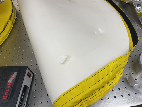
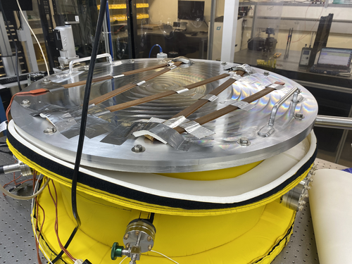
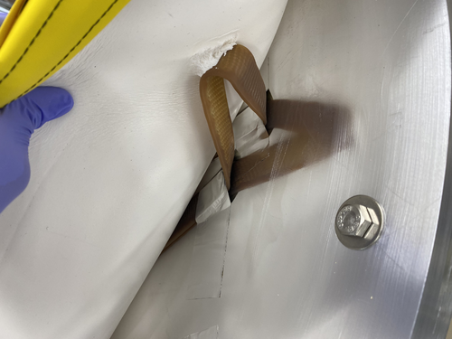
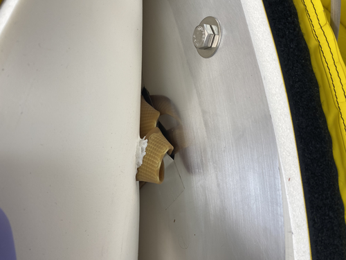
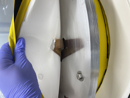
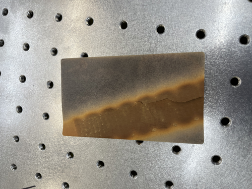
- 11:24 am: break for removal of vac chamber insulation (pictures attached), with counts before removal as seen above, and counts after removal/replacement for zone 3 as follows:
- zone 3:
- 0.3 u: 2993
- 0.5 u: 415
- 1.0 u: 207
- 12:02 pm: began surface check and wipedown
- 12:13 pm: started vacuuming the floor
- 12:25 pm: finished vacuuming the floor
- 12:26 pm: started mopping the floor
- 12:32 pm: finished mopping the floor
- 12:32 pm: started cleaning the buckets
- 12:37 pm: started mopping with IPA wipes
- 12:43 pm: finished mopping with IPA wipes
- 12:45 pm: changed sticky floor mats
- 12:47 pm: started particle count
- zone 3:
- 0.3 u: 2951
- 0.5 u: 290
- 1.0 u: 41
- zone 4:
- 0.3 u: 290
- 0.5 u: 0
- 1.0 u: 0
|
| Attachment 1: image_50412289.JPG
|
|
| Attachment 2: image_50432769.JPG
|
|
| Attachment 3: image_67126017.JPG
|
|
| Attachment 4: image_67163137.JPG
|
|
| Attachment 5: image_67168001.JPG
|
|
| Attachment 6: IMG_8427.jpeg
|
|
|
178
|
Fri Jul 28 13:39:39 2023 |
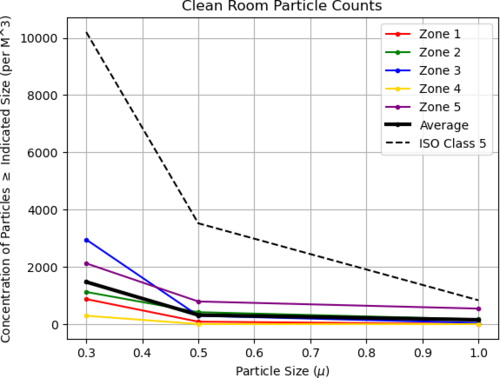
shane | Update | Cleanroom | full 5 zone cleanroom particle count |
| Here's the 5 zone cleanroom measurement from today. |
| Attachment 1: download.png
|
|
|
185
|
Tue Aug 1 12:48:41 2023 |
Aiden | Update | Cleanroom | Pre Filter Change |
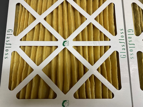
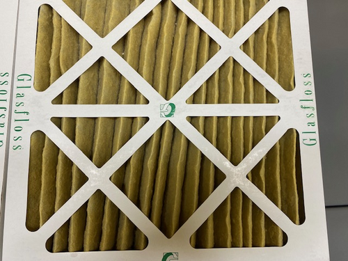
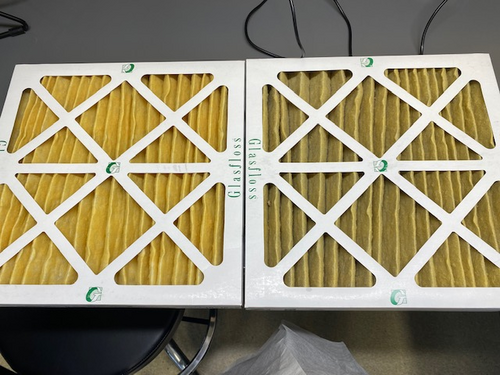
Changed the pre filter inside of the 3 stage HEPA system next to the soldering station. It was rather dirty and I have attached images with a clean filter on the left and the used one on the right. I reset the pre filter age on the system. I tried to see if I could tell if the HEPA filter was dirty but I could not see it. I did not reset the age of the HEPA or UV stations. They are currently 378 days old.
|
| Attachment 1: IMG_4564.jpg
|
|
| Attachment 2: IMG_4563.jpg
|
|
| Attachment 3: IMG_4562.jpg
|
|
|
228
|
Fri Sep 29 11:22:33 2023 |
Shane, Aiden | Update | Cleanroom | cleaning and particle count |
|
[Aiden, Shane]
cleaning cleanroom and particle count
- 10:06 am: ran zero count test on particle counter
- 10:07 am: started particle count
- zone 3:
- 0.3 u: 2203
- 0.5 u: 831
- 1.0 u: 540
- zone 4:
- 0.3 u: 374
- 0.5 u: 124
- 1.0 u: 124
- 10:25 am: began surface check and wipedown
- 10:34 am: started vacuuming the floor
- 10:44 am: finished vacuuming the floor
- 10:45 am: started mopping the floor
- 10:49 am: finished mopping the floor
- 10:50 am: started cleaning the buckets
- 10:57 am: started mopping with IPA wipes
- 11:01 am: finished mopping with IPA wipes
- 11:02 am: changed sticky floor mats
- 11:03 am: started particle count
- zone 3:
- 0.3 u: 2535
- 0.5 u: 374
- 1.0 u: 166
- zone 4:
- 0.3 u: 581
- 0.5 u: 41
- 1.0 u: 0
|
|
230
|
Fri Sep 29 11:53:54 2023 |
Shane | Update | Cleanroom | 5 zone particle count measurement in cleanroom |
| Today's 5 zone measurement of cleanroom particulate concentration is attached |
| Attachment 1: 23.png
|

|
| Attachment 2: 23.png
|

|
|
241
|
Fri Oct 20 16:38:02 2023 |
Shane, Aiden | Update | Cleanroom | Cleanrooom cleaning and particle count |
|
[Aiden, Shane]
cleaning cleanroom and particle count
|
|
259
|
Thu Nov 9 13:57:58 2023 |
Shane, Luis, Aiden, Tyler | Update | Cleanroom | cleanroom cleaning and particle count |
|
[Aiden, Shane, Luis, Tyler]
cleaning cleanroom and particle count
- 12:30 pm: Tyler and Aiden started organizing cables in cleanroom
- 12:35 pm: started particle count in flow bench
- 0.3 u: 11681
- 0.5 u: 3284
- 1.0 u: 1039
- 12:50 pm: started cleanroom particle count
- zone 3:
- 0.3 u: 14549
- 0.5 u: 10351
- 1.0 u: 6194
- zone 4:
- 0.3 u: 10808
- 0.5 u: 4655
- 1.0 u: 1953
- 1:07 pm: began surface check and wipedown, including softwalls
- 1:19 pm: started vacuuming the floor
- 1:28 pm: finished vacuuming the floor
- 1:29 pm: started mopping the floor
- 1:33 pm: finished mopping the floor
- 1:34 pm: started cleaning the buckets
- 1:37 pm: started mopping with IPA wipes
- 1:39 pm: finished mopping with IPA wipes
- 1:40 pm: changed sticky floor mats
- 1:41 pm: started particle count
- zone 3:
- 0.3 u: 8397
- 0.5 u: 5071
- 1.0 u: 2618
- zone 4:
- 0.3 u: 6651
- 0.5 u: 4323
- 1.0 u: 2120
|
|
260
|
Thu Nov 9 19:06:46 2023 |
shane | Update | Cleanroom | 5 zone cleanroom measurement |
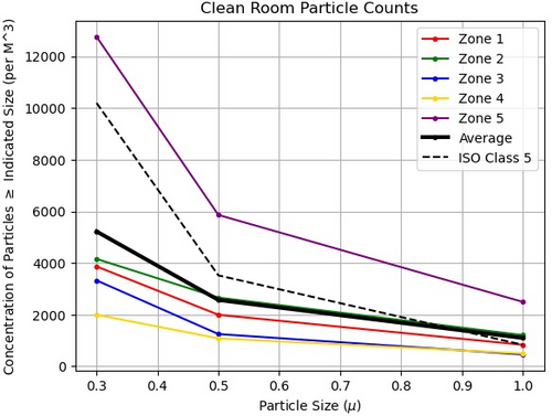
| Here's today's five zone measurement, taken ~5 hours after the cleaning. Zone 5 (closest to fire cabinet and back wall) is a bit over the limit in all size ranges (about 1500 particles in 1.0u size range over), and zone 2 is slightly over the limit in the 1.0u range, but everything else is under the requirement. |
| Attachment 1: 23.jpeg
|
|
|
262
|
Fri Nov 10 14:16:04 2023 |
shane | Update | Cleanroom | new cleanroom zone diagram |
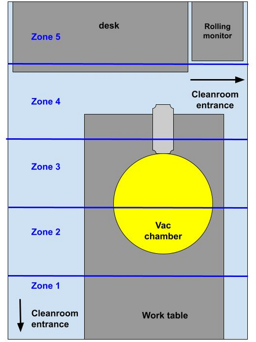
| since the vac system has been moved and made permanent, here's a new diagram of the cleanroom zones. The zones themselves haven't moved, but the diagram has been updated to reflect the new set up of the cleanroom. |
| Attachment 1: cleanroom_zones_nov2023.jpg
|
|
|
268
|
Thu Nov 16 17:12:42 2023 |
Luis, Shane, Mohak | Update | Cleanroom | Cleanroom cleaning and particle count |
|
[Shane, Luis, Mohak]
cleaning cleanroom and particle count
- 3:37 pm: started particle count
- zone 3:
- 0.3 u: 1205
- 0.5 u: 748
- 1.0 u: 249
- zone 4:
- 0.3 u: 1496
- 0.5 u: 748
- 1.0 u: 290
- 3:57 pm: began surface check and wipedown, including softwalls. NOTE: vacuum chamber insulation crumbling at edges, dropping loose flakes. Scatters residue whenever jostled, so wiping it down just releases more. Not enough flakes are being released for it to be a major issue, but definitely something to keep an eye on.
- 4:18 pm: started vacuuming the floor
- 4:29 pm: finished vacuuming the floor
- 4:30 pm: started mopping the floor
- 4:35 pm: finished mopping the floor
- 4:36 pm: started cleaning the buckets
- 4:41 pm: started mopping with IPA wipes
- 4:52 pm: finished mopping with IPA wipes
- 4:52 pm: changed sticky floor mats
- 4:53 pm: started particle count
- zone 3:
- 0.3 u: 3367
- 0.5 u: 1787
- 1.0 u: 914
- zone 4:
- 0.3 u: 1039
- 0.5 u: 498
- 1.0 u: 249
|
|
270
|
Fri Nov 17 14:06:01 2023 |
Shane | Update | Cleanroom | 5 zone particle count |
| Here's today's 5 zone particle count measurement for the cleanroom. Zone 5 (closest to back wall by fire cabinet) is still above the limit for the larger size ranges; everything else is in good shape and roughly 10 times under the limit. Not sure why zone 5 is still so dirty (maybe some of the electronics being stored in bags/bins on the upper shelf of the desk aren't clean?) but will focus cleaning efforts on this zone next time. |
| Attachment 1: 23.png
|

|
|
287
|
Thu Dec 7 14:13:15 2023 |
Shane | Update | Cleanroom | cleanroom cleaning and particle count |
|
[Aiden, Shane, Michael, Luke, Cynthia]
cleaning cleanroom and particle count
- 12:30 pm: ran zero count test on particle counter
- 12:32 pm: started particle count.
- zone 3:
- 0.3 u: 59,488
- 0.5 u: 9561
- 1.0 u: 706
- zone 4:
- 0.3 u: 7732
- 0.5 u: 1912
- 1.0 u: 290
NOTE: Frame ceiling tile collapsed in cleanroom, explaining insanely high 0.3 u particle count in zone 3 (nearly 6 times above limit). Wiped down tile and put it back in ceiling frame.
- 12:56 pm: began surface check and wipedown, including softwalls
- 1:16 pm: started vacuuming the floor
- 1:32 pm: finished vacuuming the floor
- 1:33 pm: started mopping the floor
- 1:47 pm: finished mopping the floor
- 1:48 pm: started cleaning the buckets
- 1:53 pm: started mopping with IPA wipes
- 2:05 pm: finished mopping with IPA wipes
- 2:06 pm: changed sticky floor mats
- 1:53 pm: started particle count
- zone 3:
- 0.3 u: 6401
- 0.5 u: 3450
- 1.0 u: 1787
- zone 4:
- 0.3 u: 4073
- 0.5 u: 2452
- 1.0 u: 1039
|
|
302
|
Wed Jan 10 15:27:18 2024 |
Shane | Update | Cleanroom | cleanroom cleaning and particle count |
|
[Aiden, Shane]
cleaning cleanroom and particle count
- 2:03 pm: changed sticky floor mats
- 2:05 pm: started particle count
- zone 3:
- 0.3 u: 4863
- 0.5 u: 1205
- 1.0 u: 872
- zone 4:
- 0.3 u: 1953
- 0.5 u: 789
- 1.0 u: 457
- 2:35 pm: began surface check and wipedown, including softwalls and ceiling tiles
- 2:45 pm: started vacuuming the floor
- 2:56 pm: finished vacuuming the floor
- 2:57 pm: started mopping the floor
- 3:01 pm: finished mopping the floor
- 3:02 pm: started cleaning the buckets
- 3:05 pm: started mopping with IPA wipes
- 3:08 pm: finished mopping with IPA wipes
- 3:09 pm: started particle count
- zone 3:
- 0.3 u: 5528
- 0.5 u: 2203
- 1.0 u: 1662
- zone 4:
- 0.3 u: 1080
- 0.5 u: 415
- 1.0 u: 332
|
|
309
|
Thu Jan 18 18:06:49 2024 |
shane | Update | Cleanroom | cleanroom 5 zone particle count measurement |
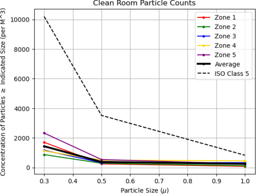
| Here's today's full five zone measurement of the cleanroom |
| Attachment 1: 24.png
|
|
|
315
|
Fri Feb 2 19:18:24 2024 |
shane | Update | Cleanroom | cleanroom cleaning and particle count |
|
[Aiden, Shane, Luis, Luke]
cleaning cleanroom and particle count
|
|
318
|
Wed Feb 7 12:43:22 2024 |
shane | Update | Cleanroom | cleanroom particle counts (full 5 zone measurement) |
| Here's today's full 5 zone measurement of the cleanroom. Everything is back under the requirement. |
| Attachment 1: 24.png
|

|
|
331
|
Tue Feb 20 11:31:49 2024 |
Tyler | Update | Cleanroom | Garment Cabinet Door Replacement |
| [Luis, Luke, Pooyan, Tyler]
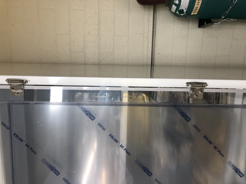
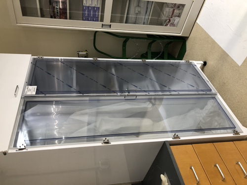
The replacement door for the HEPA garment cabinet arrived last week, and was installed on Thursday. However, it looks like there's a small gap between the door and where the hinge is attached to the cabinet frame. No screws were provided with the replacement door. If we want to perform any adjustments, we have to be very careful; the screws break very easily.
|
| Attachment 1: image_67190529.JPG
|
|
| Attachment 2: image_67177473.JPG
|
|
|
333
|
Wed Feb 21 11:58:30 2024 |
Shane | Update | Cleanroom | cleanroom cleaning and particle count |
|
[Luke, Shane, Tyler]
cleaning cleanroom and particle count
- 11:50 am: ran zero count test on particle counter
- 11:55 am: started particle count
- zone 3:
- 0.3 u: 1787
- 0.5 u: 581
- 1.0 u: 166
- zone 4:
- 0.3 u: 623
- 0.5 u: 290
- 1.0 u: 124
- 12:17 pm: began surface check and wipedown, including softwalls
- 12:25 pm: started vacuuming the floor
- 12:36 pm: finished vacuuming the floor
- 12:44 pm: started mopping the floor
- 12:57 pm: finished mopping the floor
- 12:58 pm: started cleaning the buckets
- 12:59 pm: started mopping with IPA wipes
- 1:05 pm: finished mopping with IPA wipes
- 1:06 pm: changed sticky floor mats
- 1:08 pm: started particle count
- zone 3:
- 0.3 u: 1621
- 0.5 u: 581
- 1.0 u: 332
- zone 4:
- 0.3 u: 1080
- 0.5 u: 457
- 1.0 u: 249
|
|
362
|
Wed Apr 17 15:07:04 2024 |
Shane | Update | Cleanroom | Cleanroom cleaning and particle count |
|
[Mohak, Luke, Luis, Shane, Cynthia, Michael, Xuesi]
cleaning cleanroom and particle count
NOTE: particle counter was found dead, with the charging dock unplugged. For future reference, if you need to unplug the dock, please either plug it back in when you're done, or make a note in an elog so someone else can come down and charge it.
- 1:07 pm: ran zero count test on particle counter
- 1:26 pm: started particle count
- zone 3:
- 0.3 u:1787
- 0.5 u:457
- 1.0 u:41
- zone 4: We were only able to charge the particle counter a small amount before starting the cleaning, so it died again halfway through this measurement, and we didn't get results for zone 4. In interest of time, we just put it on the charger and started the cleaning.
- 1:49 pm: began surface check and wipedown, including softwalls
- 2:16 pm: started vacuuming the floor
- 2:24 pm: finished vacuuming the floor
- 2:26 pm: started mopping the floor
- 2:32 pm: finished mopping the floor
- 2:32 pm: started cleaning the buckets
- 2:35 pm: started mopping with IPA wipes
- 2:43 pm: finished mopping with IPA wipes
- 2:43 pm: changed sticky floor mats
- 2:45 pm: started particle count
- zone 3:
- 0.3 u: 1288
- 0.5 u: 124
- 1.0 u: 0
- zone 4:
- 0.3 u: 415
- 0.5 u: 290
- 1.0 u: 0
|
|
369
|
Thu May 16 15:23:14 2024 |
Shane | Update | Cleanroom | Cleanroom cleaning and particle count |
|
[Luis, Michael, Luke, Shane]
cleaning cleanroom and particle count
- 1:45 pm: ran zero count test on particle counter
- 1:50 pm: started particle count
- zone 3:
- 0.3 u: 2660
- 0.5 u: 332
- 1.0 u: 41
- zone 4:
- 0.3 u: 8106
- 0.5 u: 2494
- 1.0 u: 831
- 2:08 pm: began surface check and wipedown, including softwalls
- 2:22 pm: started vacuuming the floor
- 2:39 pm: finished vacuuming the floor
- 2:43 pm: started mopping the floor
- 2:53 pm: finished mopping the floor
- 2:54 pm: started cleaning the buckets
- 2:59 pm: started mopping with IPA wipes
- 3:06 pm: finished mopping with IPA wipes
- 3:10 pm: changed sticky floor mats
- 3:06 pm: started particle count
- zone 3:
- 0.3 u: 1496
- 0.5 u: 83
- 1.0 u: 0
- zone 4:
- 0.3 u: 789
- 0.5 u: 83
- 1.0 u: 41
|
|
383
|
Tue Jun 25 12:34:18 2024 |
Shane | Update | Cleanroom | cleanroom cleaning and particle count |
|
[Luke, Shane, Xuejun, Mohak, Michael, Tyler, Cynthia]
cleaning cleanroom and particle count
- 10:45 am: ran zero count test on particle counter
- 11:02 am: started particle count
- zone 3:
- 0.3 u: 3284
- 0.5 u: 1247
- 1.0 u:332
- zone 4:
- 0.3 u: 1829
- 0.5 u: 581
- 1.0 u: 207
- 11:15 am: began hepavac of rest of lab
- 11:19 am: began surface check and wipedown, including softwalls
- 11:32 am: finished hepavac of rest of lab
- 11:35 am: started vacuuming the cleanroom floor
- 11:45 am: finished vacuuming the floor
- 11:47 am: started mopping the floor
- 11:55 am: finished mopping the floor
- 11:56 am: started cleaning the buckets
- 11:57 am: started mopping with IPA wipes
- 12:02 pm: finished mopping with IPA wipes
- 12:03 pm: changed sticky floor mats
- 12:04 pm: started particle count
- zone 3:
- 0.3 u: 3117
- 0.5 u: 374
- 1.0 u: 124
- zone 4:
- 0.3 u: 4531
- 0.5 u: 540
- 1.0 u: 0
|
|
388
|
Thu Jun 27 13:42:02 2024 |
Shane | Update | Cleanroom | cleanroom 5 zone particle count measurement |
| Here's today's 5 zone measurement of the cleanroom. We're above the limit by a bit in zone three (all three size ranges), likely as a result of the recent work installing FROSTI, so it could probably use another focused cleaning. Everything else is below the limit. |
| Attachment 1: 24.png
|

|
|
389
|
Fri Jun 28 10:43:13 2024 |
Xuejun | Update | Cleanroom | Frosti |
| [Xuejun, Tyler]
We moved Frosti into the cleanroom and debugged it to make sure everything was working. One of the DB25 pins broke off at the connector for element 1 so it needed to be recrimped. Element 6 short circuited but fixed with adjustment to the heater power pin position. We connected the power and sensor connectors to the power box and recalibrated the RTD sensors.
|
| Attachment 1: frosti.jpg
|
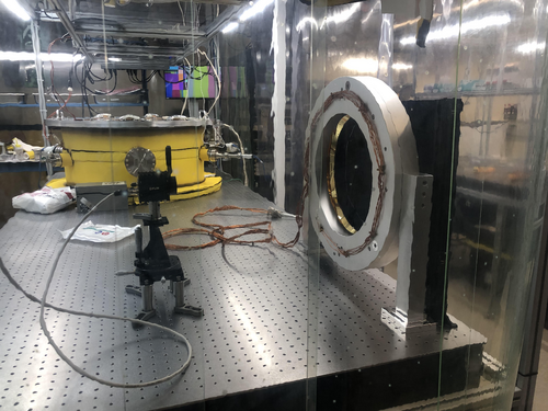
|
| Attachment 2: chassis.jpg
|

|
|
417
|
Mon Jul 29 14:30:16 2024 |
Tyler | Update | Cleanroom | RIN Measurement Set-up |
| [Tyler]
I have begun moving parts into the cleanroom for the upcoming FROSTI RIN tests that will be conducted within the next few weeks. While waiting for the rest of the equipment to arrive to perform the full-scale tests, I have additionally moved the FROSTI under the shelf above the optical table, where it will stay for the meantime. As always, please use caution when in the cleanroom. Aside from the FROSTI, the IR photodetectors that will be used for the test are delicate and costly to replace.
|
| Attachment 1: RIN_FROSTI.jpg
|
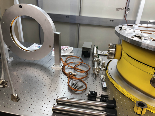
|
|
422
|
Mon Aug 12 16:24:34 2024 |
Tyler | Update | Cleanroom | RIN Measurement Update 1 |
| [Tyler]
For some preliminary tests, I moved the IR photodetectors outside of the cleanroom and onto the other optical table. The basic goal was to obtain a signal from both photodetectors. To achieve this, one of the heater cartridges used for early FLIR measurements months ago was hooked up to a power supply (PS). The PS was set to supply 0.20 A with a voltage of 2.8 V; the corresponding power is thus 0.56 W. With this, I was able to measure a signal using the Red Pitaya, the device that will be used for following RIN measurements.
| Quote: |
| [Tyler]
I have begun moving parts into the cleanroom for the upcoming FROSTI RIN tests that will be conducted within the next few weeks. While waiting for the rest of the equipment to arrive to perform the full-scale tests, I have additionally moved the FROSTI under the shelf above the optical table, where it will stay for the meantime. As always, please use caution when in the cleanroom. Aside from the FROSTI, the IR photodetectors that will be used for the test are delicate and costly to replace.
|
|
| Attachment 1: Basic_setup.jpg
|
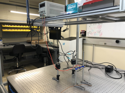
|
| Attachment 2: RP.jpg
|
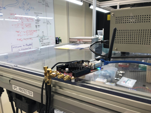
|
|
456
|
Thu Oct 3 19:35:04 2024 |
Shane | Update | Cleanroom | Cleanroom cleaning and particle count |
|
[Luke, Michael, Cynthia, Mary]
cleaning cleanroom and particle count
- 12:25 pm: started particle count
- zone 3:
- 0.3 u: 4614
- 0.5 u: 872
- 1.0 u:83
- zone 4:
- 0.3 u: 2411
- 0.5 u: 415
- 1.0 u: 83
- 12:48 pm: began surface check and wipedown, including softwalls
- 1:20 pm: started vacuuming the floor
- 1:30 pm: finished vacuuming the floor
- 1:34 pm: started mopping the floor
- 1:40 pm: finished mopping the floor
- 1:40 pm: started cleaning the buckets
- 1:42 pm: started mopping with IPA wipes
- 1:50 pm: finished mopping with IPA wipes
- 1:51 pm: changed sticky floor mats
- 3:44 pm: started particle count
- zone 3:
- 0.3 u: 3207
- 0.5 u: 624
- 1.0 u: 83
- zone 4:
- 0.3 u: 916
- 0.5 u: 83
- 1.0 u: 0
|
|
472
|
Thu Nov 14 10:46:20 2024 |
Luke | Summary | Cleanroom | Cleanroom cleaning |
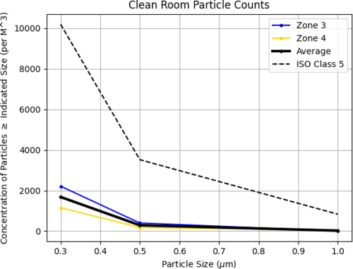
[Luke, Luis, Michael]
cleaning cleanroom and particle count
- 8:30 am: started particle count
- zone 3:
- 0.3 u: 1195
- 0.5 u: 177
- 1.0 u: 132
- zone 4:
- 0.3 u: 619
- 0.5 u: 0
- 1.0 u: 0
- 9:00 am: began surface check and wipedown, including softwalls
- 9:35 am: started vacuuming the floor
- 9:43 am: finished vacuuming the floor
- 9:45 am: started mopping the floor
- 9:55 am: finished mopping the floor
- 9:56 am: started cleaning the buckets
- 10:00 am: started mopping with IPA wipes
- 10:05 am: finished mopping with IPA wipes
- 10:20m: started particle count
- zone 3:
- 0.3 u: 2213
- 0.5 u: 398
- 1.0 u: 0
- zone 4:
- 0.3 u: 1150
- 0.5 u: 177
- 1.0 u: 44
|
| Attachment 1: partical_count_final.png
|
|
|
497
|
Wed Jan 8 17:35:57 2025 |
Luke | Summary | Cleanroom | Cleanroom cleaning |
[Luke, Tyler, Cynthia, Shane, Michael]
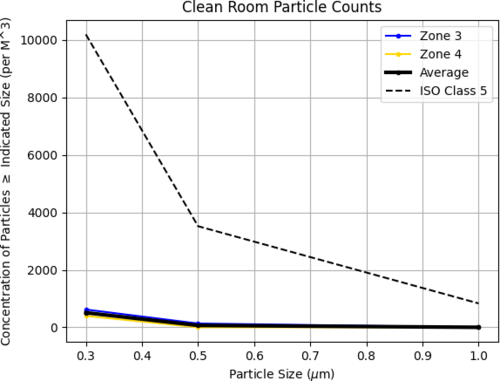
Summary of Cleaning Activities:
We began cleaning Room 1119 at 2:00 PM.
At 2:30 PM, we moved to Room 1129 and continued cleaning.
Cleaning tasks included wiping down dust-collecting surfaces and vacuuming the floors.
Once the labs were clean, we proceeded to the cleanroom.
- Wiping down surfaces and soft walls
- Vacuuming, mopping the floor, and finishing with IPA wipes
Particle Count Measurements:
- Pre-cleaning (2:30 PM):
- Zone 3:
- 0.3 µm: 973
- 0.5 µm: 354
- 1.0 µm: 132
- Zone 4:
- 0.3 µm: 486
- 0.5 µm: 177
- 1.0 µm: 0
- Post-cleaning (4:10 PM):
- Zone 3:
- 0.3 µm: 619
- 0.5 µm: 132
- 1.0 µm: 0
- Zone 4:
- 0.3 µm: 397
- 0.5 µm: 0
- 1.0 µm: 0
|
| Attachment 1: partical_count_250108.png
|
|
|
520
|
Sun Feb 23 12:11:43 2025 |
Luke | Summary | Cleanroom | Cleanroom cleaning |
[Luke, Mary, Luis]
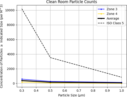
Particle Count Measurements:
- Pre-cleaning (8:40 am):
- Zone 3:
- 0.3 µm: 441
- 0.5 µm: 44
- 1.0 µm: 0
- Zone 4:
- 0.3 µm: 353
- 0.5 µm: 176
- 1.0 µm: 44
- Started Cleaning (3:16 pm)
- Finished Cleaning (4:10 pm)
- Post-cleaning (4:15 pm):
- Zone 3:
- 0.3 µm: 574
- 0.5 µm: 265
- 1.0 µm: 132
- Zone 4:
- 0.3 µm: 177
- 0.5 µm: 44
- 1.0 µm: 0
|
| Attachment 1: partical_count_2-21-25.png
|
|
|
574
|
Fri May 9 20:06:27 2025 |
Luke | Summary | Cleanroom | Cleanroom cleaning |
[Luke, Mohak, Luis]
We were also able to remove the residue that has built up on the soft walls by donning a skinny bunny suit and with two wipes rubbing both sides of the soft walls at the same time. The wipes would get gummy very quickly and need to be replaced frequently.
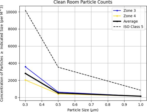
Particle Count Measurements:
- Pre-cleaning (1:20 pm):
- Zone 3:
- 0.3 µm: 3577
- 0.5 µm: 1369
- 1.0 µm: 485
- Zone 4:
- 0.3 µm: 1062
- 0.5 µm: 442
- 1.0 µm: 177
- Started Cleaning (3:00 pm)
- Finished Cleaning (4:00 pm)
- Post-cleaning (4:22 pm):
- Zone 3:
- 0.3 µm: 3577
- 0.5 µm: 618
- 1.0 µm: 132
- Zone 4:
- 0.3 µm: 2031
- 0.5 µm: 397
- 1.0 µm: 132
|
| Attachment 1: 20250509_particalcount.png
|
|
|
580
|
Wed May 21 14:40:38 2025 |
Xuesi Ma | Infrastructure | Cleanroom | Cleanroom Temperature |
|
Date and Time: Around 2:20 PM on May 21, 2025
Location and Temperature:
- Back of the room, around the working station: 85.5 °F
- Front of the room, around the doorway: 82.3 °F
|