| ID |
Date |
Author |
Type |
Category |
Subject |
|
283
|
Sat Dec 2 18:10:23 2023 |
Aiden | Update | VAC | VAC System Heating Update |
| [Aiden]
Turned off the heating tape today in anticipation to take more RGA data on Sunday or Monday morning before the meeting. |
|
284
|
Mon Dec 4 11:19:50 2023 |
Aiden | Update | VAC | Vacuum Chamber Baking Update |
| [Aiden]
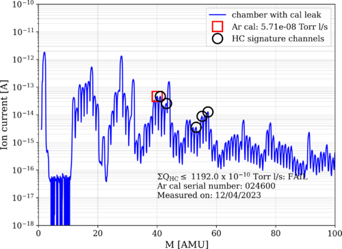
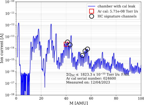
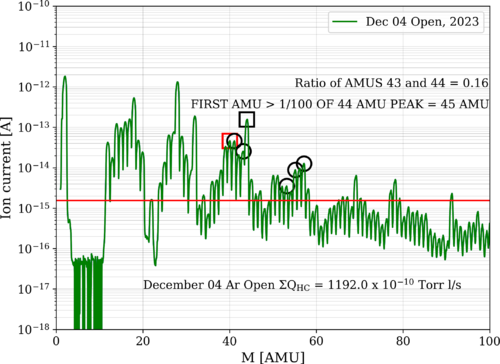
Took some RGA data of the chamber after it has been cooling down. I do not believe that this data accurately shows the HC levels in the chamber as the pressure is still above where it was at before the bake and was still falling. I believe more time is needed to let the pressure fall and for the RGA filament to remain on to return to a point where the data can be trusted. |
| Attachment 1: bake8_231204_SSFasteners_ArO.png
|
|
| Attachment 2: bake8_231204_SSFasteners_ArC.png
|
|
| Attachment 3: December_04_Ar_Open_Stainless_Steel_Fasteners_Analyzed.png
|
|
| Attachment 4: bake8_231204_SSFasteners_ArO.png
|

|
|
286
|
Thu Dec 7 12:42:42 2023 |
Aiden | Update | VAC | Vacuum Chamber Baking Update |
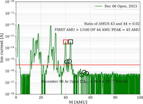
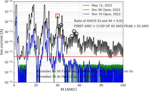
| After leaving the RGA on for a few days the chamber has settled at 2.01 e-8 torr. I also have good news that the chamber looks to be even cleaner as the HC levels are now the lowest they have been being at 26 e-10 Torr l/s. |
| Attachment 1: December_06_Ar_Open_Stainless_Steel_Fasteners_Analyzed.png
|
|
| Attachment 2: bake8_231206_SSFasteners_ArO.png
|
|
|
292
|
Fri Dec 15 14:03:02 2023 |
Aiden | HowTo | VAC | Vacuum Chamber Opening |
| [Aiden]
1. Turn off the RGA filament and disconnect it.
2. Record the pressure and then close the angle valve and gate valve on the RGA line to isolate it from the system.
3. Turn off the backing and turbo pump and let the turbo pump spin to a stop by slowly leaking the chamber. The slower the safer.
4.Slowly open the vents on the chamber and the turbo pump. Making sure not to raise the pressure too fast.
5. Once done venting the chamber, open the lid by removing the bolts and prying the lid open with a long flat head screw driver.
6. Removed previous parts and placed them into clean bags. Place new parts inside of the chamber and group them together close to the center.
7. Place the lid back onto the chamber and tighten the bolts in a circular pattern until tightened all the way with the wrench.
8. Make sure all vents are closed and turn the backing pump back on.
9. The turbo pump can be turned back on when the pressure reaches e-1 torr.
10. Wait until the chamber reaches a pressure of e-6 torr before opening the angle and gate valve on the RGA line. After the RGA line is open and the pressure is still below e-6 torr, the RGA filament can be turned on and a leak test of the lid should be performed.
11. After the leak test shows no leaks, proceed with starting the low temp bake. |
|
293
|
Sun Dec 17 19:43:18 2023 |
Aiden | Update | VAC | Vac Heating Update |
| [Aiden]
I measured the temperature of the flanges where some of the electronics will go and I found that the RGA flange was at 55C and the two full range gauges were at 65C. I also stopped bake 9 to cool down for measurement. |
|
295
|
Mon Dec 18 15:51:49 2023 |
Aiden | Update | VAC | VAC System Heating Update |
| After letting the chamber cool down I put the electronics back on and turned the RGA element back on. No data has been taken yet as to let the pressure continue to fall as the RGA is powered. |
|
296
|
Tue Dec 19 15:45:05 2023 |
Aiden | Update | VAC | Vacuum Chamber Baking Update |
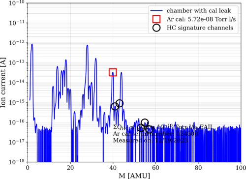
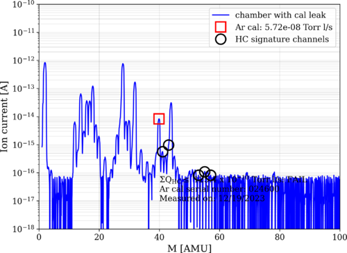
| Took RGA data for the macor parts inside of the chamber. With the Ar open the HC levels read 30 torrl/s which is around where it was before the bake. |
| Attachment 1: bake9_231219_Macor_ArO.png
|
|
| Attachment 2: bake9_231219_Macor_ArC.png
|
|
|
301
|
Tue Jan 9 16:35:09 2024 |
Aiden | Update | VAC | VAC System Leak and Heating |
| [Luis, Luke, Aiden]
Leak tested each flange and weld and only found two flanges to have noticeable leaks with the electron multiplier on. These were the turbo pump flange and the RGA flange that connects to the cross. The RGA one is rather new as it has not had a measurable leak before and it was around 2 e-8. We then applied the new sealant to these two flanges as directed by the instructions on the packaging.
Then after waiting a few minutes for the sealant to dry we started the bake. We got the PID controllers set to 120 after many steps and we checked the temperature of the flanges throughout this increase. The flanges never reached 70C with the electronics still left on it. The RGA was left on as well. |
|
306
|
Tue Jan 16 16:11:41 2024 |
Aiden | Update | VAC | |
| [Aiden,Luis]
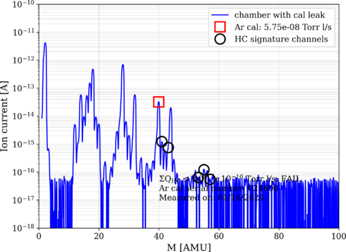
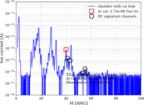
Below is the data for the most recent bake. I believe the chamber is cleaner than it is actually showing as the RGA data was still getting lower while the data was being taken. I will take the data again tomorrow just in case. Still, the data shows that the chamber is basically as clean as it was before bake 10 and this means further power testing can proceed.
Helium leak tested the chamber again today to check if the sealant changed anything. The two primary target flanges from last time have improved significantly with the flange from the RGA on the cross now being below 2e-14. While the turbo pump flange was leaking at a rate of 4e-13. Much better than what it has been before. |
| Attachment 1: bake10_240116_Elements_ArO.png
|
|
| Attachment 2: bake10_240116_Elements_ArC.png
|
|
|
308
|
Thu Jan 18 15:13:37 2024 |
Aiden | Update | VAC | VAC Heating System Update |
| [Aiden]
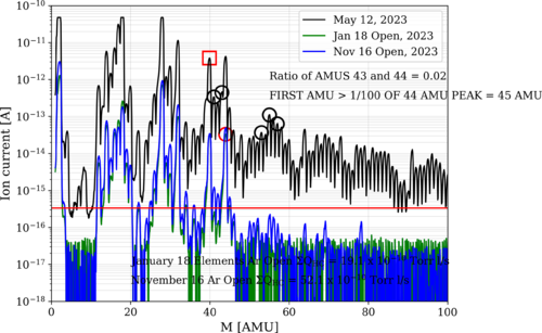
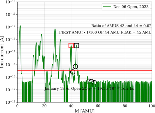
Took more data today and the chamber and elements are showing an even lower HC level than we have gotten before. It is safe to say that the elements are not contaminated and out gassing HC into the chamber. |
| Attachment 1: bake10_240118_Elements_ArO.png
|
|
| Attachment 2: January_18_Ar_Open_Elements_Analyzed.png
|
|
|
314
|
Fri Feb 2 19:08:20 2024 |
Aiden | Update | VAC | 1st Hot Element RGA Scan |
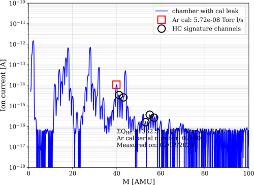
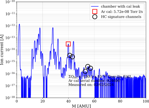
| Here are the measurements for the RGA scan of the elements while on at around 160C. The pressure of the chamber during the test was 4.12 e-8 torr. |
| Attachment 1: bake10_240202_Elements_ArC.png
|
|
| Attachment 2: bake10_240202_Elements_ArO.png
|
|
|
316
|
Mon Feb 5 14:17:52 2024 |
Aiden | Update | VAC | Heater Element RGA Scan |
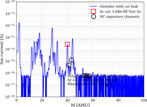
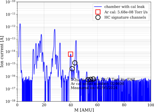
| Here are the new RGA scans for the powered Heater elements. The pressure at the time of taking data was 2.88 e-8 torr. The HC levels are at 40 e-10 torrl/s which is not bad but still higher than the lowest we have recorded. |
| Attachment 1: bake10_240205_Elements_ArO.png
|
|
| Attachment 2: bake10_240205_Elements_ArC.png
|
|
|
319
|
Thu Feb 8 17:37:48 2024 |
Aiden | Update | VAC | Heater Element RGA Scan |
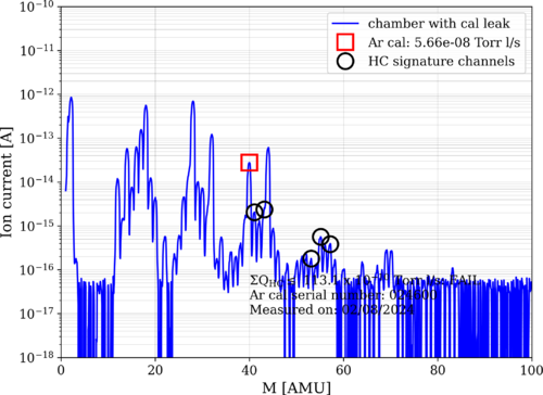
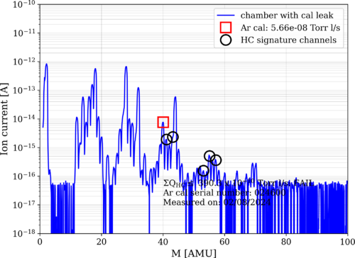
| Took more RGA data now that the heaters are powered by 18V. The pressure of the system during the data taking was 3.8 e-8 torr. The RGA scans seem to have gotten worse as well with this power increase. |
| Attachment 1: bake10_240208_Elements_ArO.png
|
|
| Attachment 2: bake10_240208_Elements_ArC.png
|
|
|
320
|
Mon Feb 12 17:35:47 2024 |
Aiden | Update | VAC | Heater Element RGA Scan |
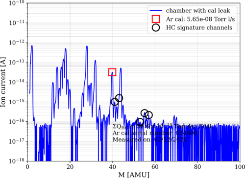
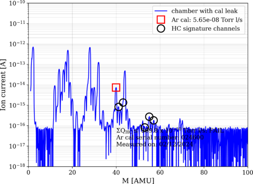
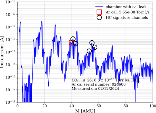
| Took more RGA data before and after increasing the heater elements to 300 degC and before heating them up.
Started Bake 11 as well to hopefully prevent any hydrocarbons from getting captured by the room temperature walls of the chamber. The PID controllers were set to 100C. |
| Attachment 1: bake10_240212_Elements_ArO.png
|
|
| Attachment 2: bake10_240212_Elements_ArC.png
|
|
| Attachment 3: bake10_240212_Elements_300C_ArC.png
|
|
|
325
|
Tue Feb 13 12:34:04 2024 |
Aiden | Update | VAC | VAC Heating System Update |
| Here is an overlay with for all the heating steps done with the heater elements. |
| Attachment 1: bake10_240118_Elements_ArO.png
|

|
|
327
|
Fri Feb 16 18:37:28 2024 |
Jon | Update | VAC | Bake ended 6:23 pm |
I ended the bake of the UHV system (that began on Monday) at 6:23 pm today by switching OFF both PID controllers. The heaters elements were run at max power (24 V DC / 200 mA per element) during this bake, and I left them powered at the same level.
At the time, the instrument readings were as follows:
- Left high-limit controller: 138 C
- Right high-limit controller: 128 C
- Left PID controller: 100 C
- Right PID controller: 100 C
- Main volume pressure: 8.17e-7 Torr
- RGA volume pressure: 4.63e-7 Torr
|
|
328
|
Mon Feb 19 14:17:50 2024 |
Aiden | Update | VAC | Heater Element RGA Scan |
| Three days after the completion of Bake 11, the Heater elements RGA scan looks much cleaner. The HC level is back down to 33 e-10 torrl/s with the pressure at 2.13 e-8 torr. I could not take a= scan with the Argon closed as it was left open during the bake and not closed since then. |
| Attachment 1: bake11_240219_Elements_ArO.png
|
|
|
335
|
Thu Feb 22 21:48:16 2024 |
Jon | Update | VAC | Vacuum vent for RGA testing of reflector |
[Jon, Tyler, Luke, Aiden]
Summary
Following Wednesday's cleanroom cleaning [333], we proceeded to vent the vacuum chamber, remove the heater elements and their mount structure, and install the FROSTI reflectors. The reflectors are the final components to undergo RGA testing before the FROSTI prototype can be assembled. After installing the reflectors, we pumped the chamber back down and initiated a 48-hour 125 C bake.
Vacuum Vent
At ~1:00 pm, we shut off power to all eight of the FROSTI heater elements. Prior to shutoff, all were operating in vacuum at roughly 300 C. We then waited approximately 30 minutes for the elements' temperatures to fall below 50 C.
At this point, we isolated the RGA volume from the main volume by closing both gate valves, leaving the RGA volume to continue to be pumped through the bypass line. We then backfilled the main volume via the needle valve connected to one of the 2.75" ports. Once the pressures had equalized, we removed the chamber lid via our usual procedure (requiring only a small amount of flathead-screwdriver prying) and extracted the heater element assembly.
Reflector Assembly
We then removed the FROSTI reflectors from their protective packaging (for the very first time) on the cleanroom tabletop. We tested the fit of the Macor and stainless steel hardware in the reflectors' tapped holes. The Macor standoffs and bolts appear to fit perfectly. However, the 1/4-20 tapped holes for joining the two reflector halves are too shallow by ~1/4". As a temporary fix, we used some on-hand stainless steel washers (which had already been cleaned and baked) to securely fasten the two halves together. In the final assembly we will replace these with slightly shorter 1/4-20 vented bolts.
Pumpdown and Bake
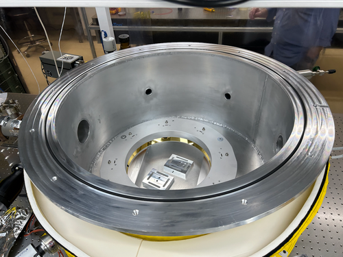
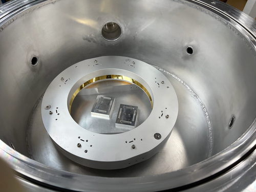
The two fastened reflector halves were placed inside the chamber, sitting on top of the two mounting legs (see attached photos). We then reinstalled the lid. In order to rough the main volume, we isolated the RGA volume from the pumpline (by closing the bypass line valve), shut down the pumps, and then backfilled the pumpline via the manual vent valve on the turbo pump.
Once the pressures had equalized, we opened the 6" gate valve separating the pumpline from the main volume and powered on the roughing pump. Once the main volume pressure fell below 0.5 Torr, we powered on the turbo pump as well. The main volume pressure reached 5e-6 Torr within ~30 minutes, consistent with previous experience, and was continuing to slowly fall.
Lastly, we initiated a 125 C bake-out of the entire system following our usual procedure. We plan to run this bake for 48 hours (i.e., through the end of the day Friday). |
| Attachment 1: IMG_0938.png
|
|
| Attachment 2: IMG_0939.png
|
|
|
348
|
Fri Mar 15 16:58:55 2024 |
Aiden | Update | VAC | Vacuum Chamber Frosti Testing |
| [Luke, Luis, Aiden]
On Thursday, March 14 - Took preliminary RGA scans of the empty chamber to compare later on. Vented the chamber and placed the FROSTI into the chamber. Plugged in the DB-25 connectors into the feed through port and checked the connection to make sure there were no shorts before closing the chamber and starting the pumps again.
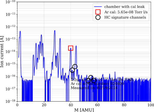
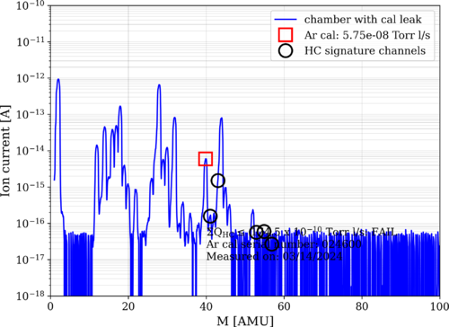
On Friday, March 15 - The pressure in the chamber has come down to 7 e-6 torr. It seems to be coming down much slower despite the little time the chamber was left open for. This may be due to the FROSTI being out on the table for so long and a bake may be needed to bring the pressure down to near UHV. |
| Attachment 1: bake12_240314_Empty_ArC.png
|
|
| Attachment 2: bake12_240314_Empty_ArO.png
|
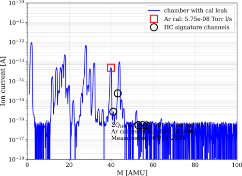
|
|
367
|
Mon May 13 14:48:27 2024 |
Aiden | Update | VAC | New Vacuum Chamber Design |
| I created a new model for the vacuum chamber based on the ideas from last week's meeting.
It should be noted that we can not have the zero length reducer and the gate valve on the same arm as they both have blind tapped holes. We need to decide if we want the gate valve or not as if we do, we will need to use the 3 inch long reducer.
Important Measurements:
From the back of the flange to the back of the RGA: 25.25 in
Height from bottom of the blank to the bottom of the chamber: 2.75 in |
| Attachment 1: VaccumChamberAssembly__Redesign_v5.jpg
|
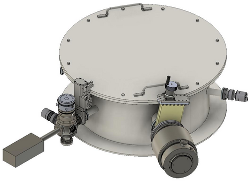
|
|
372
|
Mon Jun 3 09:24:48 2024 |
Aiden | Update | VAC | Vacuum Chamber Rendering |
| Here is a new render of the vacuum chamber that includes the 2.75 tee to place the Argon leak right next to the RGA. The conical reducer under the spherical cube was also replaced with a 4.5 blank. The height from the bottom of the blank to the bottom face of the chamber is 5.45". With the chamber now on 1" standoffs, we will need a support with a height of 6.45". |
| Attachment 1: VaccumChamberAssembly__Redesign_with_tee.jpg
|
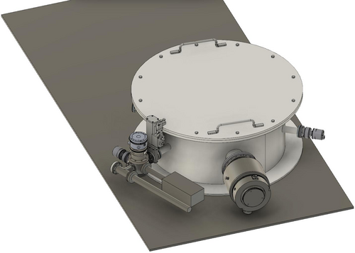
|
| Attachment 2: VaccumChamberAssembly__Redesign_with_tee_top.png
|
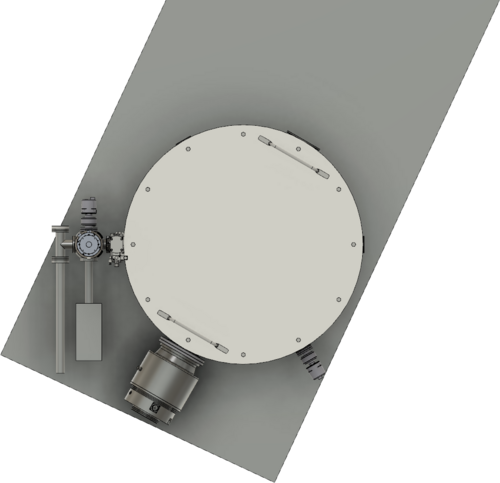
|
|
384
|
Tue Jun 25 17:19:42 2024 |
Luke | Update | VAC | Vacuum chamber leak checking |
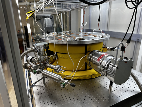
| Currently our main leak is in the RGA line. We found this by closing the gate valve from the main volume to see if which side was leaking more.
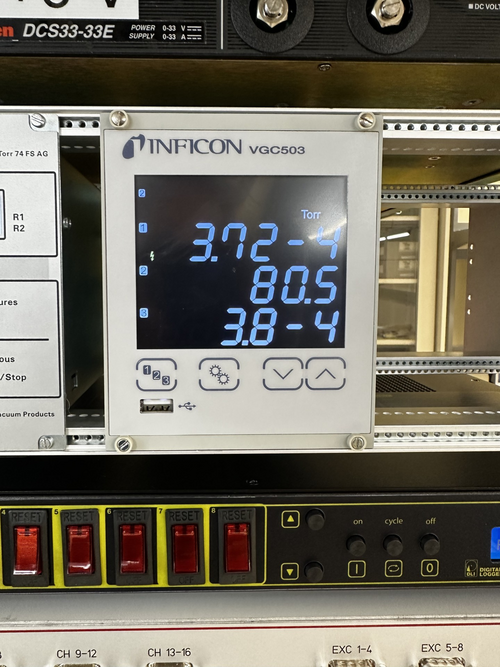
After identifying this we are pumping down the main volume to see how low it can go the third attachment was taken at 4:16 6/25/24. Pumping started around 3:15.
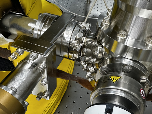
We have not been able to find exactly which flange is leaking, but our guess is on the small blanks and where the cube attaches to the gate valve as seen in the second attachment.
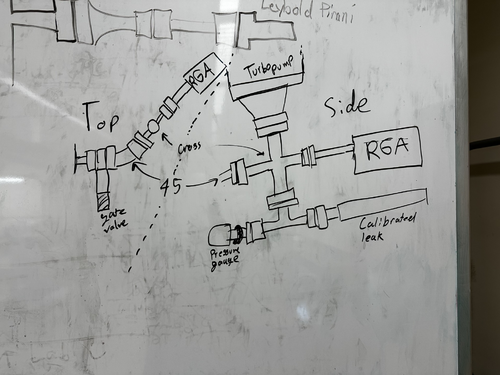
We will try a few more things and if the leak is not found/fixed we are planning on changing the configuration of the RGA line to remove the spherical cube, which we believe to be the problem. See fourth attachment for rough sketch of initial idea.
We have all of the parts required and they are clean and double bagged in 1129. I have not yet made all the measurements to confirm that this design is feasible. |
| Attachment 1: image_2024-06-25_170036021.png
|
|
| Attachment 2: image_2024-06-25_170057738.png
|
|
| Attachment 3: image_2024-06-25_170120030.png
|
|
| Attachment 4: image_2024-06-25_171238788.png
|
|
|
386
|
Wed Jun 26 16:39:34 2024 |
Luke | Update | VAC | Vacuum chamber leak checking |
| On Tuesday I had isolated the main volume and let it pump down over-night. Today, Wednesday, I checked it and it had only gone down by a small amount compared to when I left it on Tuesday.
I then proceeded to tighten down the bolts attaching the tubo-pump to the zero-length reducer while it was under vacuum. This caused the pressure to drop down a few orders of magnitude. |
| Attachment 1: image_2024-06-26_162539705.png
|
|
| Attachment 2: image_2024-06-26_162601616.png
|
|
|
390
|
Fri Jun 28 18:15:16 2024 |
Luke | Update | VAC | Vacuum chamber |
We will be configuring the RGA line to remove the spherical cube from the system. Currently our plan for the new design is to connect a 4.5" to 2.75" Reducing Cross to the gate valve on the vacuum system. It will be orientated vertically with the turbo pump on top coming off the end will be a 90 deg elbow. On the bottom there will be a 4.5" to 2.75" Zero length reducer attached to that will be a Tee on one side the pressure sensor and the other the RGA. Connected to the elbow will be the calibrated leak.
The only parts not readily available are the ZLR and the 2.75" gaskets
| Part name |
Count needed |
Status/comment |
| 2.75" Tee |
1 |
In use in current RGA line |
| 4.5" to 2.75" Reducing Cross |
1 |
Needs to be clean and baked |
| 4.5" to 2.75" Zero length reducer |
1 |
To be purchased |
| 2.75" 90 deg elbow |
1 |
Clean needs to be removed from another part |
| 5/16 - 24 X 2.00" Bolts and nuts |
16 |
8 in clean room and plenty in storage they will need to be clean and baked. Plenty of nuts in clean room.
|
| 1/4 - 28 X 1.25" Bolts and nutplates |
24 |
12 in use in RGA line and 12 in storage that will need to be clean and baked. Sufficient nutplates in clean room |
| 1/4 - 28 X 7/8" Bolts |
12 |
Plenty of bolts in clean room |
| 2.75" Copper Gasket |
6 |
5 gaskets in clean room and none in storage. So some will need to be purchased |
| 4.5" Copper Gasket |
2 |
About 10 in clean room |
|
|
400
|
Wed Jul 10 17:31:07 2024 |
Luke | Update | VAC | RGA line disassembly and upgrade |
[ Luke, Cynthia, Michael, Xuesi, Anthony ]
Started work around 12:45
We vented the chamber first and once it reached atmospheric pressure we started taking apart the RGA line.
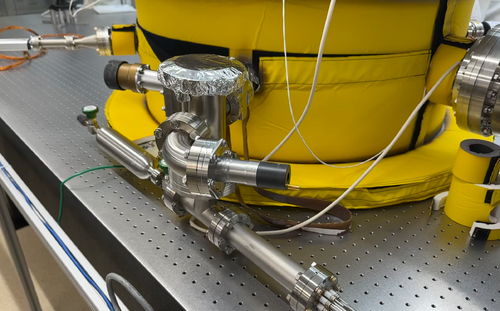
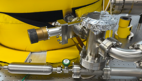
We removed the parts in this order: Calibrated leak, RGA, Pressure gauge, 2.75" Blank on Tee, 2.75" Tee, all 1.33" Blanks on the cube, 4.5" feed through port, and finally the cube. Everything went smoothly after every part was taken off we covered the ends in Aluminum foil to maintain cleanliness.
We then started the assembly of the new line. The parts were added in this order: Reducing cross, ZLR, Tee, Cal leak, RGA, 90 deg Elbow, and Pressure sensor.
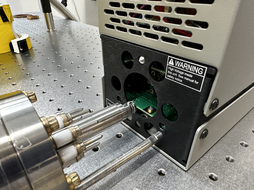
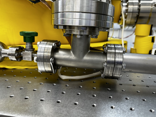
We left off the Turbo pump as of now because we weren't able to find a 1" post not in use and we didn't want to put too much weight on the cross. We also noticed that the RGA might not fit on its probes because of a slight tilt to the cross and by extension the Tee. If this ends up being a problem we might need to remove all the parts connected to the cross so that we can reposition it so that the 2.75" rotating flange is connected to the gate valve.
Ended work around 4:00 |
| Attachment 1: image_2024-07-10_172112210.png
|
|
| Attachment 2: image_2024-07-10_172431863.png
|
|
| Attachment 3: image_2024-07-10_172603090.png
|
|
| Attachment 4: image_2024-07-10_172823966.png
|
|
|
401
|
Thu Jul 11 15:53:39 2024 |
Luke | Update | VAC | RGA line upgrade |
[ Luke, Jon ]
Started work at 11:00
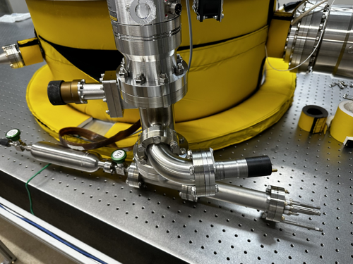
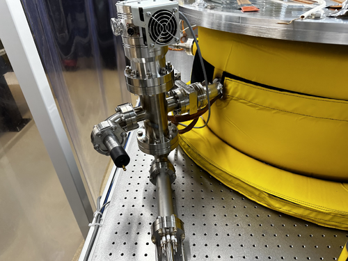
As mentioned in my previous post the RGA was not clearing the table because of a tilt in the cross. So I removed the 90 deg elbow, loosened the bolt securing the Tee to the ZLR, and removed the cross from the gate valve. I then spun around the Tee on the bottom so that the cal leak would be pointing in the right direction and connected the rotating 2.75" flange of the cross to the gate valve. I then added the small turbo pump to the top of the cross.
Then with the help of Dr. Richardson, we made some adjustments to how the Tee was oriented with respect to the cross and how the cross was with respect to the table. So that the cal leak and RGA would fit on the table. After that we made some changes to the bolting of the ZLR to reducing cross replacing the 2.00" bolts and nuts with 1.75" bolts and nut plates. We did face some difficulty with half of the 2.00" bolts which required a bit of torque to get them out.
Finished work at 2:20
Things to do:
Before we start pumping down the system again Dr. Richardson wanted two other changes to be made. To replace the 2.75" to 1.33" conical reducer with a zero length reducer. He also wants the bolts that hold the main turbo pump to be replaced with nut plates.
I plan on starting this work on Friday (7/12) before pumping down over the weekend |
| Attachment 1: image_2024-07-11_154630323.png
|
|
| Attachment 2: image_2024-07-11_154818191.png
|
|
| Attachment 3: image_2024-07-11_154902840.png
|
|
|
405
|
Mon Jul 15 13:30:49 2024 |
Luke | Update | VAC | Problem with 2.75" to 1.33" zero length reducer |
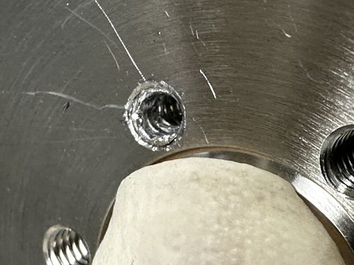
| Last Friday while checking the depth of the ZLR I got one of the screws stuck. Today I tried a couple things to get it out. First I tried a few different pliers to be able to grip lower on the screw this didn't work. So I switched to the other method of drilling a small hole to see if maybe the threads would pull away from the walls of the hole a bit. This kind of worked as seen in the picture below I was able to remove most of the screw but there is a bit still stuck which I was not able to remove and I didn't want to use a larger bit for fear of damaging the tapped hole. |
| Attachment 1: IMG_1882.jpg
|
|
|
411
|
Mon Jul 22 18:19:34 2024 |
Luke | Update | VAC | Zero length reducer stuck bolts |
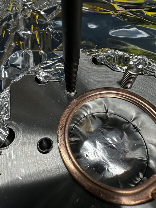
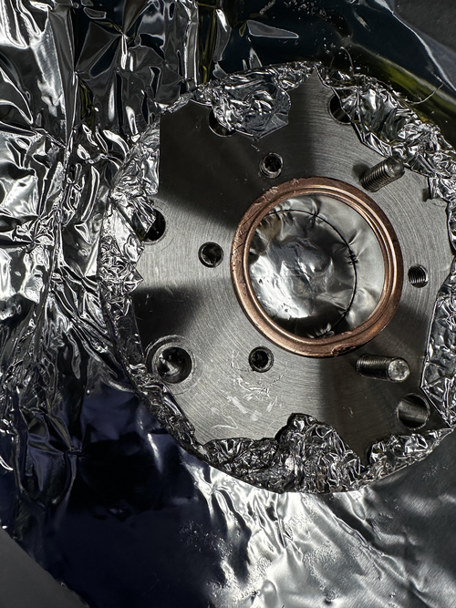
Today, I borrowed a bolt extractor drill bit from the machine shop to remove some stuck bolts from the zlr. Before starting, I laid down a sheet of aluminum foil on the work table and wiped down all the tools I was going to use. I began by drilling a small pilot hole and then enlarged it with a 5/32 drill bit. However, when I attempted to use the bolt extractor, it didn't grip the bolt effectively. Our bolts were too seized, causing the extractor bit to repeatedly slip instead of gaining traction. |
| Attachment 1: image_2024-07-22_181607501.png
|
|
| Attachment 2: image_2024-07-22_181632965.png
|
|
|
425
|
Fri Aug 16 12:51:46 2024 |
Luis Martin | Update | VAC | Update on vacuum chamber status |
[Luis, Luke, Tyler]
Vacuum chamber parts were finally received and assembled. After whipping down the parts, the blank was removed from the reducing cross. Then, the zero-length reducer was attached. Lastly, we installed the T that had the argon leak and RGA. The final pump down showed signs of an improved seal since the pressure dropped quite fast. This pressure is well bellow the limit required to use the RGA, argon test leak could be performed some time next week. |
| Attachment 1: IMG_1910.HEIC
|
| Attachment 2: IMG_1911.HEIC
|
| Attachment 3: IMG_1909.HEIC
|
| Attachment 4: IMG_1912.HEIC
|
|
427
|
Fri Aug 23 16:08:32 2024 |
Luke | Update | VAC | RGA line leak testing |
[Luke, Luis, Jon, Tyler]
On the 22nd Dr. Richardson showed Luis, Tyler and I how to preform a leak test with the RGA. We did the initiall test and found a few leaks two were particuarly bad highlighted in orenge below. To try and remidy this we planned on replacing the copper gaskests on the leaking flanges. We then began taking the two problem flanges off, but seven of the eight bolts holding on the turbo pump were over tightened and had seized. So after we got them off we postponed the rest of the work to the next day.
On the 23nd Luis and I reattached the badly leaking flanges with new copper gaskets. We then preformed the Helium leak test with the RGA. As seen in the table below we weren't able to majorly changed the leaks in the two flanges.
| Connection |
Initial |
After disassembly |
| Tee - RGA |
3.1e-9 -> 2.4e-9 |
9.2e-9 |
| Tee - Cal leak |
Low |
Low |
| Tee - ZLR (2.75"-4.5") |
Low |
9.2e-9 |
| ZLR (2.75"-4.5") - Reducing Cross |
2.1e-8 -> 1.9e-8 |
3.6e-8 -> 9.3e-9 |
| Cross - Elbow |
Low |
1.2e-9 |
| Elbow - Pressure sensor |
Low |
2.9e-9 |
| Cross - Turbo pump (small) |
2.1e-8 -> 3.1e-8 |
6.9e-8 -> 2.2e-8 |
| Cross - Gate valve |
Low |
Low |
| Gate valve - Port |
2.4e-9 -> 2.2e-9 |
1.2e-9 |
| Port - ZLR (6.0"-8") |
1.1e-9 |
N/A |
| ZLR (6.0"-8") - Turbo pump (large) |
Low |
N/A |
| Port - Pressure sensor |
Low |
N/A |
| Port - Up to air valve |
Low |
N/A |
| Port - Blank |
Low |
N/A |
| Port - Feed though port |
Low |
N/A |
| Lid |
Low |
N/A |
|
|
429
|
Tue Aug 27 15:01:26 2024 |
Luke | Update | VAC | RGA line leak testing |
[Luke, Tyler]
On the 27th Tyler and I ran the RGA leak test again with the electron multiplier on. These were the leaks we measured. The chamber's overall pressure was at ~6e-8 torr.
| Connection |
Leak rate (torr) |
| Tee - RGA |
3.92e-11 (very low) |
| Tee - Cal leak |
4.77e-11 (very low) |
| Tee - ZLR (2.75"-4.5") |
4.97e-11 (very low) |
| ZLR (2.75"-4.5") - Reducing Cross |
2.45e-9 (low) |
| Cross - Elbow |
7.36e-11 (very low) |
| Elbow - Pressure sensor |
2.36e-11 (very low) |
| Cross - Turbo pump (small) |
8.07e-9 (lowish) |
| Cross - Gate valve |
4.02e-11 (very low) |
| Gate valve - Port |
2.27e-9 (low) |
| Port - ZLR (6.0"-8") |
1.11e-9 (low) |
| ZLR (6.0"-8") - Turbo pump (large) |
1.00e-10 (very low) |
| Port - Pressure sensor |
1.05e-10 (very low) |
| Port - Up to air valve |
1.08e-11 (very low) |
| Port - Blank |
5.58e-10 (very low) |
| Port - Feed though port |
1.21e-11 (very low) |
| Lid |
1.11e-11 (very low) |
|
|
431
|
Thu Aug 29 16:39:34 2024 |
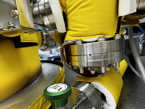
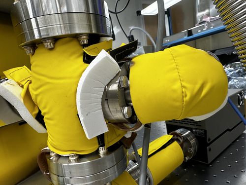
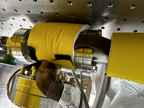
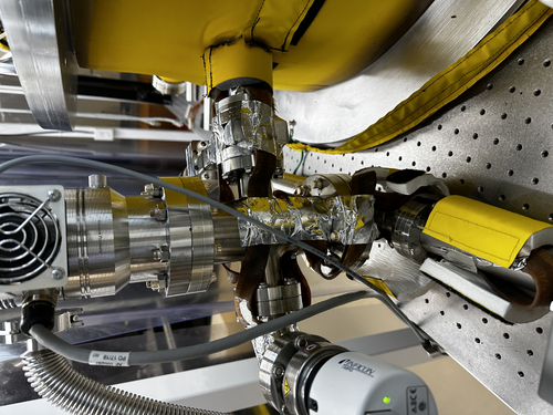
Luke | Update | VAC | Photos of heater tape |
|
| Attachment 1: IMG_2052.jpeg
|
|
| Attachment 2: IMG_2051.jpeg
|
|
| Attachment 3: IMG_2048.jpeg
|
|
| Attachment 4: IMG_2047.jpeg
|
|
| Attachment 5: IMG_2046.jpeg
|
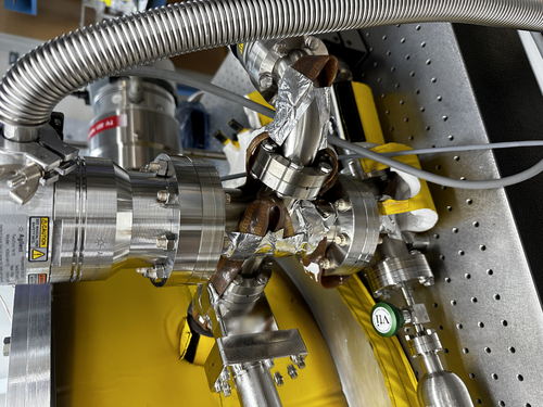
|
| Attachment 6: IMG_2044.jpeg
|
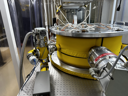
|
|
432
|
Sun Sep 1 16:17:40 2024 |
Luke | Update | VAC | Vacuum chamber leak checking and re-applying heating tape |
[Luke, Luis, Cinthia, Michal, Tyler]
On the 26th Cinthia, Michal, and I took off the insolation on the vacuum chamber and re-routed it to include the new RGA volume.
The next day Luis and I finished up the last of the flanges to be attached. We attached the Pirani gauge with a conical reducing nipple to the 2.75" port on the vacuum chamber. We then preformed the Helium leak testing, both flanges were quite low the 2.75" flange had a leak of 1.68e-10 torr and the 1.33" flange of 5.5e-12 torr. The leak on the 1.33" flange was so low it was difficult to know how much of it was real and how much was just noise. |
|
433
|
Tue Sep 3 15:52:56 2024 |
Luke | Update | VAC | Heater tape initilization |
[Luke, Tyler, Jon]
On the 3rd we set up the pid controllers for the heater tapes and after putting on the insulation we started heating them up. We first brought it to ~50C and let it stabilize, there was about a 6-7 degree difference between the RGA and the barrel temperature, with the barrel being higher. We then brought it to 60 then 70C it still maintained the slight difference between the RGA and barrel temperatures.
Here is a table of the temperatures of the flanges connected to electronics as I left it.
| Electronics |
Temperature (C) |
| Pressure gauge (Main volume) |
58 |
| Main turbo pump |
45 |
| RGA |
37 |
| Pressure gauge (RGA volume) |
39 |
| Cal leak |
40 |
| Mini tubo pump |
36 |
| Pirani gauge |
37 |
Notes: I removed the electronics from the pressure gauge (main volume) because while it was below the required threshold it was still quite high compared to the other flanges. |
|
435
|
Fri Sep 6 14:34:52 2024 |
Luke | Update | VAC | Heating tape work |
On the 5th I had tried to start baking the vacuum chamber however certain parts of the chamber were getting too hot and causing the controllers to shut off. So I turned them off so that the next day I could rearrange the temperature probes. I then on the 6th set them up so that instead of overshooting the temperature they would be a little low in places.
After being left over night the cooler parts of the vacuum chamber got much closer to the desired temperature of 120C.
Here is a table of the temperatures of the sections of the chamber. Note: After these measurements were taken the PID controllers were set to 125C.
| Location |
Temperature (C) |
| Lid (PID controller 1 emergency shutoff) |
108 |
| Barrel lower (PID controller 1) |
120 |
| Barrel upper (PID controller 2 emergency shutoff) |
118 |
| RGA volume (PID controller 2) |
120 |
Here is a table of temperature of the flanges that have electronics.
| Electronics |
Temperature (C) |
| Pressure gauge (Main volume) |
79 |
| Main turbo pump |
64 |
| RGA |
51 |
| Pressure gauge (RGA volume) |
55 |
| Cal leak |
47 |
| Mini turbo pump |
50 |
| Pirani gauge |
45 |
Other temperatures of note:
The optical table was about 38C
The cleanroom was around 33C (~91F) |
|
438
|
Mon Sep 9 21:02:37 2024 |
Luke | Update | VAC | Steadystate temperature of flanges |
I measured the temperature of the flanges and reconnected the RGA turning on its filament. I then turned off the PID controllers.
Here is a table that has the temperature of the different parts of the vacuum chamber.
| Electronics |
Temperature (C) |
| Pressure gauge (Main volume) |
81 |
| Main turbo pump |
67 |
| RGA |
53 |
| Pressure gauge (RGA volume) |
60 |
| Cal leak |
48 |
| Mini tubo pump |
46 |
| Pirani gauge (1.33") |
46 |
| conical nipple (2.75") |
82 |
| Lid |
112 |
| Barrel lower |
125 |
| Barrel upper |
122 |
| RGA volume |
125 |
| Bottom of chamber |
117 |
|
|
440
|
Mon Sep 16 13:51:23 2024 |
Luis Martin | Update | VAC | RGA Scans |
|
[Luis, Luke}
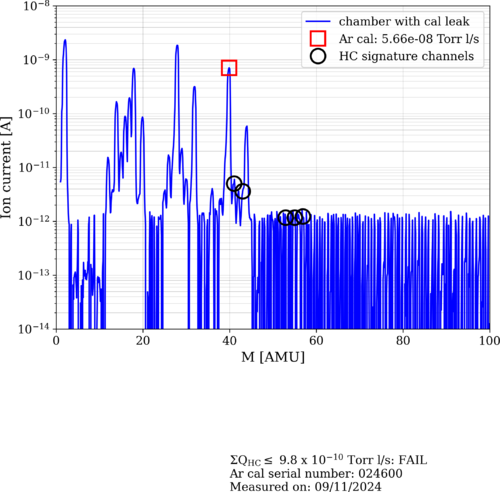
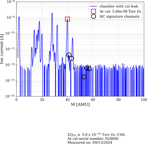
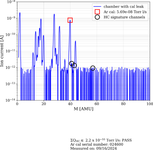
Three RGA scans were taken. The improvement in the amount of HC in the vacuum is visible across the different measurements. Images are attached.
|
| Attachment 1: 2024-09-11_PostBake1_ArO.png
|
|
| Attachment 2: 2024-09-13_PostBake1_ArO.png
|
|
| Attachment 3: 2024-09-16_PostBake1_ArO.png
|
|
|
448
|
Wed Sep 25 09:06:09 2024 |
Luis Martin | Update | VAC | RGA Scans |
|
RGA Scan Comparison
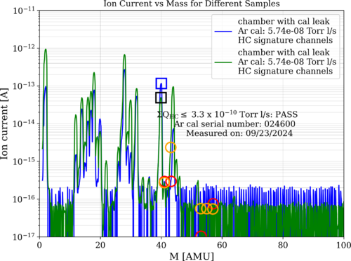
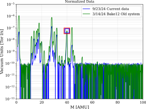
The following images compare the RGA scans from 9/23/24, after the first bake with the new vacuum system, with those from 3/14/24, after bake 12 with the old system.
The first image shows a graph of the raw data and includes the calibrated leak for both curves. As we can see, our new system meets LIGO standards of cleanliness.
The second graph contains the plot of the normalized data.
|
| Attachment 1: 24overlay.png
|
|
| Attachment 2: 24overlayNormalized.png
|
|
|
459
|
Wed Oct 16 13:58:59 2024 |
Luis Martin | Update | VAC | RGA Scan |
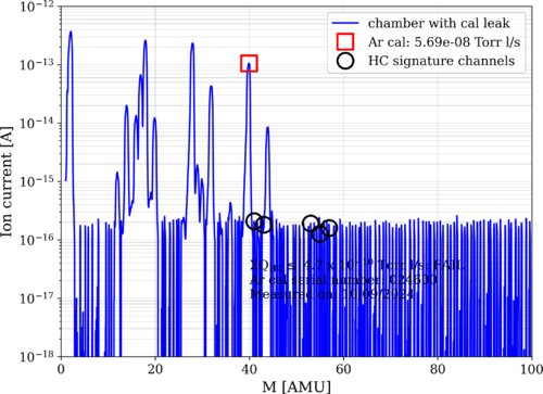
The following figure displays data acquired on 10/09, and it shows that we are no longer below the cleanliness standard. Also, the system's pressure went up to 1.9x10⁻⁸ Torr (approximately 7x10⁻⁹ Torr previously). This might be due to a leak somewhere in the system. More tests will be performed later. |
| Attachment 1: 2024-10-09_PostBake1_ArO.png
|
|
|
462
|
Wed Oct 23 11:48:06 2024 |
Luis Martin | Update | VAC | Leak Test Results |
[Luke, Luis, Mary, Ma]
On 10/22/24 Luke, Ma, Mary and myself ran a leak test, the results are displayed below. The overall pressure of the vacuum was 2.0e-8 and the temperature readings were 26C for the RGA and 25C for the main volume.
| Connection |
Leak rate (torr) |
| Tee - RGA |
9.4e-12 (very low) |
| Tee - Cal leak |
1.58e-11 (very low) |
| Tee - ZLR (2.75"-4.5") |
7.32e-12 (very low) |
| ZLR (2.75"-4.5") - Reducing Cross |
6.9e-11 (low) |
| Cross - Elbow |
2.34e-11 (very low) |
| Elbow - Pressure sensor |
1.96e-11 (very low) |
| Cross - Turbo pump (small) |
1.91e-9 (lowish) |
| Cross - Gate valve |
1.66e-10 (very low) |
| Gate valve - Port |
7.41e-10 (low) |
| Port - ZLR (6.0"-8") |
2.93e-10 (low) |
| ZLR (6.0"-8") - Turbo pump (large) |
6.15e-11 (very low) |
| Port - Pressure sensor |
2.0e-11 (very low) |
| Port - Up to air valve |
1.42e-11 (very low) |
| Port - Blank |
1.27e-11 (very low) |
| Port - Feed through port |
4.59e-12 (very low) |
| Lid - Curtain side |
3.09e-11 (very low) |
| Lid - Wall side |
4.26e-11 (very low) |
|
|
463
|
Wed Oct 23 12:08:36 2024 |
Luis Martin | Update | VAC | RGA Scan |
[Luke, Luis, Mary, Ma]
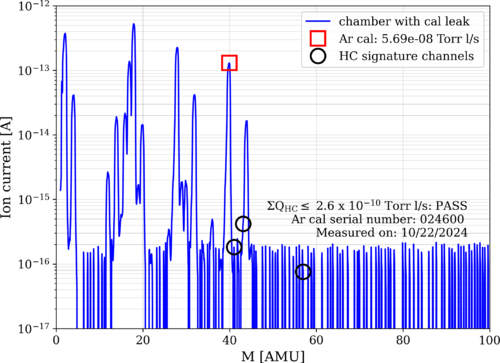
On 10/22/24 Luke, Ma, Mary and myself ran a RGA scan, the results are displayed below. The overall pressure of the vacuum was 2.0e-8 and the temperature readings were 26C for the RGA and 25C for the main volume.
As we can see, the vacuum is passing cleanliness standards again. |
| Attachment 1: 2024-10-22_PostBake1_ArO.png
|
|
|
468
|
Tue Nov 5 11:08:40 2024 |
Luis Martin | Update | VAC | ISO Test |
|
[Luis, Luke, Ma Michael]
The isolation test was conducted on the vacuum system. Every pump was turned off under vacuum, and pressure measurements were taken every minute for 15 minutes. The results are displayed in the sheet linked at the end of this report. The pressure of the main volume dropped very slowly.
The pressure of the RGA Volume dropped in an exponential manner. The test had to be paused at 11 minutes due to concerns about the pressure exceeding the lowest permitted level for the RGA filament.
After the ISO test was performed, we attempted to tighten the bolts of the small turbo pump on the RGA Volume. However, we noticed that the pressure had increased by nearly an order of magnitude, going from 3.27 × 10⁻⁹ Torr to 1.45 × 10⁻⁸ Torr when both volumes were separated. We conducted a leak test for that particular flange and found a concerning leak of 2.15 × 10⁻⁸ Torr, which had previously been 1.9 × 10⁻⁹ Torr. We believe the copper seal was damaged during the ISO test.
View the results sheet
|
|
474
|
Tue Nov 19 17:10:34 2024 |
Luke | Update | VAC | Leak check |
Chamber temperature: 23C
Chamber Initial Pressure: ~1.8e-8 main, ~3.5e-8 rga
Did another leak test after monday's work to check how the seal was holding up initial leak was 5.5e-9. I then tried to tighten the bolts a bit more the leak rose to 1.9e-8 about a factor of 4 change.
I checked another flange to confirm that I was preforming the test properly. I measured the elbow to pressure sensor to be 2.2e-11 aproximatly what it was earlier in the month (1.9e-11).
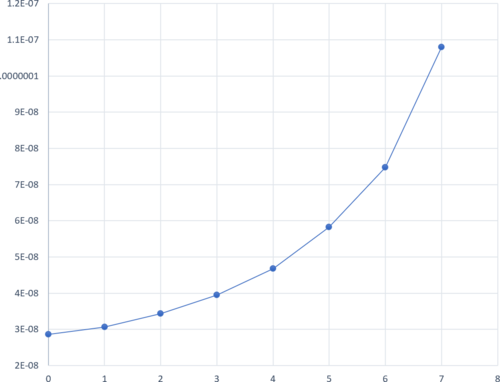
I ran another isolation test. It is still exponetial. Graph attached.
Thoughts:
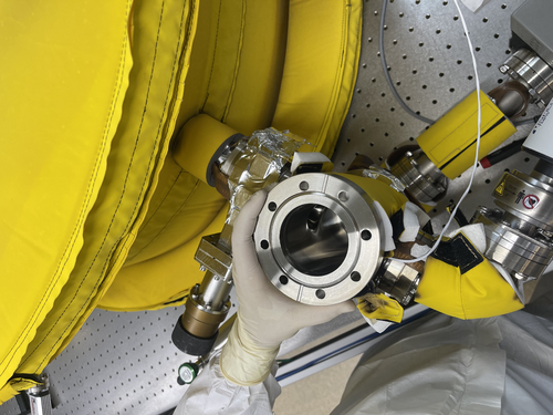
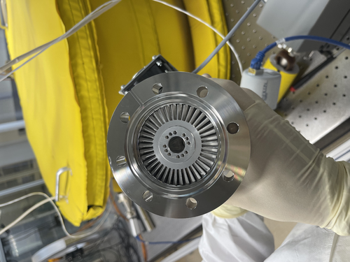
I belive at this point that it is a knife edge issue when replacing the gasket I checked both flanges and the new gasket. The tp knife edge seemed perfectly fine, the gasket had very minor scratches, and the reducing cross had very small imperfections on its edge.
We may want to try and use the liquid sealant or get annealed gaskets for 4.5" |
| Attachment 1: image.png
|
|
| Attachment 2: IMG_5116.jpeg
|
|
| Attachment 3: IMG_5117.jpeg
|
|
|
476
|
Wed Nov 20 12:31:24 2024 |
Luis | Update | VAC | Leak test RGA Scan after vacuum repairs |
[Luke, Luis]
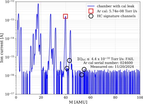
After the gasket replacement performed on Monday (11/18/24) we let the vacuum pump down to UHV pressure for a couple days. Today (11/20/24) we measured the pressure to be 5.30*e^-9 with a temperature of 22C, and we performed a leak test and RGA Scan.
Here are the results:
| Connection |
Leak rate (torr) |
| Reducing Cross - TP Left |
4.5e-9 (lowish) |
| Reducing Cross - TP Right |
6.0e-9 (lowish) |
|
| Attachment 1: 2024-11-20_PostBake1_ArO.png
|
|
|
478
|
Wed Nov 27 12:27:45 2024 |
Luke | Summary | VAC | Summary of vacuum work |
[Luke, Luis]
Update of current state of vacuum chamber
Current temp: 24°C
Current pressure: Main 1.77e-8, RGA 5.3e-9 [torr] (Gate valve open)
Summary of recent work-->
To try and reduce the leak in the turbo pump by reducing cross-connection, we replaced the copper gasket. This made no improvement to the leaks.
Initially: 1.9e-9 --->
Left side: 1.33e-9, Right side: 3.37e-9 (Gate valve open)
This is still a significant leak. We have tried to tighten the bolts further, but they are as tight as reasonably possible.
Things of note: While examining the knife edges, we found some very slight imperfections on the reducing cross's flange as seen in 474. This could be the source of our leak. We have replaced this gasket 1-2 times already and consistently have a slight leak. This imperfection is on the right side of the flange, which would be consistent with the measurements above.
Unless we want to use the liquid sealant or replace the gasket with an annealed gasket, we could try baking the system again, as this allowed us to reach UHV in the main volume before. It also allowed us to pass the RGA scan, which we are currently failing. (see attached) |
| Attachment 1: 2024-11-27_PostBake1_ArO.png
|

|
|
480
|
Wed Nov 27 16:23:58 2024 |
Luke | Update | VAC | Started bake |
[Luke, Luis]
The vacuum chamber is currently baking.
We stepped up to 125°C by increments of 30°C starting at 60°C. Everything went fine. After about 20 minutes of the PID controllers being set to 125°C, the flange closest to the RGA was 38°C, so we left it connected.
Current state as of 4:15:
The gate valve is open, and the filament of the RGA is on.
The temperatures are as follows:
PID right barrel upper: 105°C, RGA volume: 125°C
PID left barrel lower: 125°C, Lid: 82°C
The lower temperatures should climb as the whole system heats up.
I will come in Saturday afternoon to turn them off so that we can look at the pressures on Monday. |
|
481
|
Sat Nov 30 12:41:42 2024 |
Luke | Update | VAC | Vacuum bake end |
The vacuum chamber has stopped bakeing.
Current state as of 12:10, 11/30/2024:
The gate valve is open, and the filament of the RGA is on.
The temperatures were steady at:
PID right: barrel upper: 128°C, RGA volume: 125°C
PID left: barrel lower: 125°C, Lid: 113°C
The RGA flange was 38°C
Cleanroom was 26°C |
|
485
|
Thu Dec 5 10:31:13 2024 |
Luis | Update | VAC | RGA Scan and RGA updates |
|
[Luis,Shane]
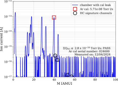
An RGA scan was taken on Dec 4th. The results are attached at the end of the e-log. As we can see, the scan results are under the allowed limits. After the scan, Shane and I worked on the vacuum connections. The filament was turned off, and the RGA was disconnected from Spica.
After we finished the tests, we reconnected the RGA and attempted to turn the filament back on. However, the program was unable to connect to the instrument. We checked for any loose connections but did not find anything. The RGA connection needs to be troubleshot and fixed.
|
| Attachment 1: 2024-12-04_PostBake2_ArO.png
|
|
|
487
|
Wed Dec 11 16:06:05 2024 |
Luis | Update | VAC | RGA Status |
[Luis]
I rebooted Spica and I was able to connect the RGA again. After Connecting the RGA, I left the filament on. |
|
488
|
Thu Dec 12 13:06:39 2024 |
Luis | Update | VAC | RGA Scan and vacuum system updates |
| [Luis, Luke]
RGA Volume: T = 21°C, P = 1.74e-9 Torr
Main Volume: T = 22°C, P = 5.60e-9 Torr
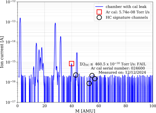
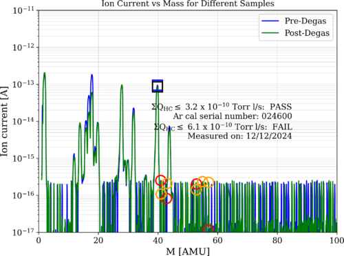
We performed an RGA scan of the system. As we can see, we met cleanliness standards. The S/N ratio was roughly calculated and it is about 100. I will update the code to make this calculation and to have it displayed on the plot in the next scan we perform.
After this, we closed the RGA to the main volume valve, degassed the filament, and after the pressure came down to what it was initially, we reopened the valve. After the degassing, we took another scan. The overlaid plots are attached below.
The noise floor seemed to be about the same. I will take another scan tomorrow to verify whether it was the same or if the system just needed a little more time to be completely clean. |
| Attachment 1: 2024-12-12_PostBake2_ArC.png
|
|
| Attachment 2: 2024-12-12_PostBake2_ArO_overlay.png
|
|