| ID |
Date |
Author |
Type |
Category |
Subject |
|
105
|
Tue May 23 16:52:56 2023 |
Pamella | Update | FLIR | FLIR project - Reinstalling the mask and Reconfiguration FLIR position. |
[Pamella]
Reinstalling the mask and Reconfiguration FLIR position.
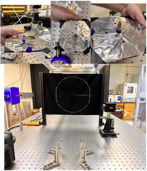
- Today i change the aluminum foil inside the 3D mask. After some tries i was able to have a better shape for the triangles.
- I reinstalled the connections (the light with the thermometer point). Also i checked for the focal point inside the reflector, looks fine.
- I did a reconfiguration for the initial tests, without the black wall. I moved the FLIR camera and the Reflector-Mask for other position on the table.
To do:
- Start the test with the power current on.
- I need figure out a better position for the light cables because in front of the mask isn't a good position for us do measurement.
|
| Attachment 1: AcquisitionImage(May-23-2023_16_36).jpg
|
.jpg.png)
|
| Attachment 2: Reconfiguration.jpg
|
|
|
149
|
Thu Jul 6 18:03:19 2023 |
Pamella | Update | FLIR | FLIR project - New configuration |
[Pamella]
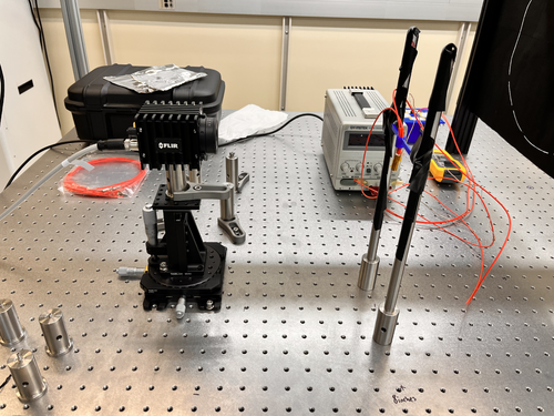
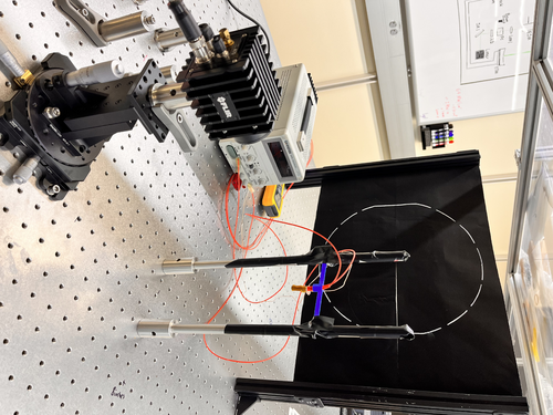
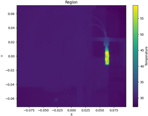
Cao suggested using the project without the reflector and mask because in this case we probably got good images around the screen. So I started this yesterday and today I started to get some data to see the stabilization position and check how the parameters fluctuated. I was looking and taking snaps for an hour and a half. I'll repeat this one more time to make sure we have enough data to do analysis.
To do: The next step is to start collecting data by moving the camera FLIR and covering all six positions on the screen (2x3). Also Aiden is on hand to help and is going to make a new 3D print bridge to have good heater support.
I attached a image for the new configuration below and a snap data. |
| Attachment 1: IMG_8193.jpeg
|
|
| Attachment 2: IMG_8183.jpeg
|
|
| Attachment 3: AcquisitionImage(Jul-06-2023_17_18)_(1).jpg
|
_(1).jpg.png)
|
| Attachment 4: region_temperature1.jpg
|
|
|
104
|
Mon May 22 17:08:50 2023 |
Pamella | Update | FLIR | FLIR project - Installing the mask. |
[Pamella]
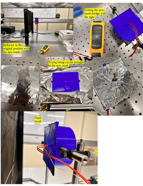
- The new mask for the reflector.
- 1:40 pm: Started reconfiguration on the FLIR camera project. Changed the old bridge for the new mask-bridge.
- 2:00 pm: Started figure out the best way to cutting the aluminum foil with the new mask. Unfortunately, I had been some problems for cutting the perfect shape triangles with the mask because the size inside the triangle is different (smaller) than cutter/knife, so is not able to do the cut with precious and carefully then maybe I need other tool for this job. Also I tried use the scissor, didn't work. However, just for the initial testing I worked with the not perfect triangles shape.
- 2:49 pm: Started installing/attaching the light in the mask.
- 3:21 pm: Finished installing the light in the mask-bridge.
- 3:22 pm: Started testing the current and voltage in the new mask-bridge for make sure the light cable is working well.
- 3:25 pm: Started measurement the resistance with multimeter.
- 3:29 pm: The measurement looks fine. The multimeter show us 14.1 Ω;
- 3:38 pm: Started putting the reflector( with the mask attached) in front of the black wall.
- 3:44 pm: Started roll the testing with the python code to observer the behavior with this new mask. Parameters: 0.14 A and 1.9 V.
- 4:00 pm: Started snapping. Parameters: 0.13 A and 1.9 V. Final Temperature: 42.7 C.
- 4:02 pm: Started trying again with more current. Parameters: 0.16 A and 2.2 V.
- 4:36 pm: Started snapping. Parameters: 0.16 A and 2.2 V. Final Temperature: 50.3 C.
- 4:55 pm: For now, we can't see the triangles in the snap so i need do some changes.
- To do:
- Change the FLIR camera position for the other side on the table.
- Start the test without the black wall.
- Try a better tool to cut the triangles inside the 3D-mask.
|
| Attachment 1: Mask.jpg
|
|
| Attachment 2: AcquisitionImage(May-22-2023_16_35).jpg
|
.jpg.png)
|
| Attachment 3: AcquisitionImage(May-22-2023_16_01).jpg
|
.jpg.png)
|
|
58
|
Wed Mar 29 16:00:36 2023 |
Pamella | Update | Cameras | FLIR project |
|
Today Pamella and Tyler started work in the updates for the FLIR project.
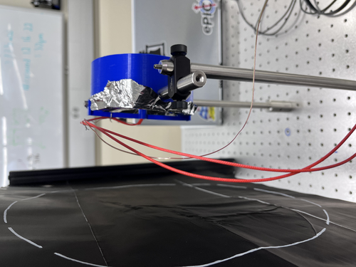
We trie for the first time cover the mirrors with aluminum foil and run the code with this.
We work in figured out how the python codes works with real datas.
To do:
Understand how get the real datas and how to compere that with the old datas.
Starting test with the FLIR and mirrors with aluminum foil in with the power on.
Testing the FLIR camera more times with the mirrors covered with aluminum foil. |
| Attachment 1: 15D13FE3-48A9-4ACF-9422-07032DD8D028.jpeg
|
|
|
73
|
Wed Apr 19 17:39:50 2023 |
Pamella | Update | FLIR | FLIR project |
FLIR project updates- Initial tests
- 10:00: Starting test in position 2 cm to the black wall.
- Parameters : 0,305 A, 05,5 V and the temperature inside the mirrors 141,8°C.
- 10:23 Finished this first tried and take snap. The image is attached below.
- The name for the picture for this tried is “AcquisitionImage(Apr-19-2023_10 23)”.
- 10:37. Starting test in another position now 3 cm distance to the black wall ( this is more close than the original position.)
- Parameters : 0,348 A, 05,5 V and the temperature inside the mirrors 160,3°C.
- 10:57 Finished this second tried and take a snap. The image is attached below.
- The name for the picture for this tried is “AcquisitionImage(Apr-19-2023_10 57)”.
- 11:03 Starting test another position 1.3 cm distance to black wall.
- Parameters : 0,347 A, 05,5 V and the temperature inside the mirrors 158,7°C.
- 11:18 Finished this second tried and take a snap. The image is attached below.
- The name for the picture for this tried is “AcquisitionImage(Apr-19-2023_11 18)”.
The next step should be fix the problem with the shape (aluminum foil lid).
|
| Attachment 1: AcquisitionImage(Apr-19-2023_10_23)(1).jpg
|
(1).jpg.png)
|
| Attachment 2: AcquisitionImage(Apr-19-2023_10_57)_(1).jpg
|
_(1).jpg.png)
|
| Attachment 3: AcquisitionImage(Apr-19-2023_11_18)_(2).jpg
|
_(2).jpg.png)
|
|
143
|
Mon Jul 3 18:38:13 2023 |
Pamella | Update | FLIR | FLIR project |
[Pamella]
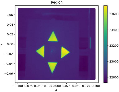
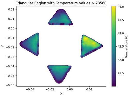
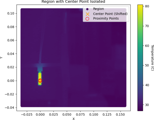
- I was able to work on the python code to do analysis on the FLIR-Reflector data.
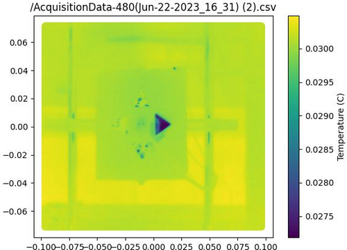
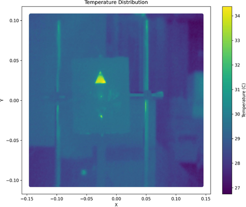
- I could plot images of total area (Tyler help me on that) with csv file and also could have isolation area for triangles. I have attached examples below. Just for now the images are of different data, so there are some differences in the shapes.
- I'm working on getting a complete analysis code to work with the different positions of the triangles and to be able to do out the statistical analysis.
- Also we keeping have problem to get good data if when we move the camera or the reflector on horizontal or vertical position. I am working a some ideas for that.
|
| Attachment 1: Region.jpg
|
|
| Attachment 2: triangular_region_temperature-2.jpg
|
|
| Attachment 3: heatmap.jpg
|
|
| Attachment 4: isolation1-4.jpg
|
|
|
442
|
Mon Sep 16 14:59:51 2024 |
Tyler | Update | TCS | FLIR RIN Update 09/16 |
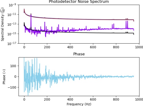
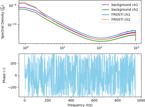
Below is the dark noise spectrum of the Red Pitaya, which was measured over the course of a weekend. Additionally, I have successfully measured a signal from the photodetectors with the FROSTI as the IR source, so it seems there shouldn't be any worry of these particular detectors not being feasible for the RIN measurement. |
| Attachment 1: adc_noise_floor_photodectors.png
|
|
|
3
|
Thu Jun 2 21:55:02 2022 |
Jon | Update | Cameras | FLIR Camera Setup |
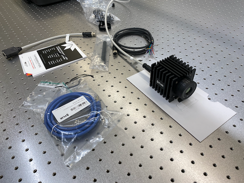
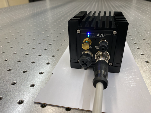
The new FLIR A70 infrared camera has arrived. Tyler and I unpacked it in the lab yesterday. In less than an hour, we succeeded in powering it on and connecting it to the lab network. We have assigned it the static IP address 192.168.1.6.
Online Configuration Portal
The FLIR camera can be configured, as well as stream live data, through a web browser interface. It can be accessed from any workstation on the lab network by navigating in the browser to http://192.168.1.6. The login credentials are stored here (log in with your LIGO.ORG credentials).
Next Steps
The next step is to install FLIR's Python API for controlling and reading out the camera on chimay. The API comes with demo codes which we can use to test the basic connectivity and which will serve as a reference for developing our own Python interface over the summer. |
| Attachment 1: IMG_1473.png
|
|
| Attachment 2: IMG_1474.png
|
|
|
4
|
Fri Jun 3 13:03:33 2022 |
Jon | Update | Cameras | FLIR Camera Setup |
Summary
I have installed the requisite software on chimay for interfacing the FLIR A70 camera in Python. There are two packages required from FLIR:
- Spinnaker SDK, which provides the low-level camera drivers and a C/C++ API.
- PySpin, a wrapper of the Spinnaker library which provides the Python API.
These installations did not work out-of-the-box for Debian 11 (only Ubuntu is officially supported). I had to make several modifications which are documented below for future reference.
This setup has not yet been tested with the camera connected to chimay.
Documentation and Demo Codes
The PySpin package comes with a number of Python demo codes and a complete API reference. These can be found on chimay at the following locations.
- Example codes:
/opt/spinnaker/python/Examples/Python3/
- Python API reference manual:
/opt/spinnaker/python/docs/PySpinDoc.pdf
Installing Spinnaker SDK
Below were the steps required to install Spinnaker on chimay (Debian 11).
- Download the Spinnaker binaries (AMD64 architecture) and copy the tarball to, e.g.,
/home/controls on chimay.
- Unpack the tarball contents and enter the new directory:
$ tar -xf spinnaker-2.6.0.160-Ubuntu20.04-amd64-pkg.tar.gz
$ cd spinnaker-2.6.0.160-amd64
$ sudo apt-get install libavcodec58 libavformat58 \
libswscale5 libswresample3 libavutil56 libusb-1.0-0 \
libpcre2-16-0 libdouble-conversion3 libxcb-xinput0 \
libxcb-xinerama0
qt5-default, which is obsolete in Debian and no longer available via the package manager (that is, its functionality was absorbed into other Qt packages). I was able to find a workaround based on these instructions.
- Install all the dependencies of
qt5-default:
$ sudo apt-get install qtbase5-dev qtchooser qt5-qmake qtbase5-dev-tools
- Manually remove the
qt5-default dependency from the Spinnaker package.
Unpack the spinview-qt_2.6.0.160_amd64.deb package:
$ mkdir tmp
$ cd tmp
$ ar -x ../spinview-qt_2.6.0.160_amd64.deb
$ tar xf control.tar.xz
Open the file control in a text editor and delete the qt5-default dependency from the Depends list.
Then repackage the contents:
$ tar cfJ control.tar.xz control
$ ar rcs ../spinview-qt_2.6.0.160_amd64.deb debian-binary control.tar.xz data.tar.xz
$ cd ..
$ rm -rf tmp
qt5-default dependency.
- Now proceed with running the install script:
$ sudo sh install_spinnaker.sh
This will install the Spinnaker library at /opt/spinnaker. Spinnaker also provides a standalone GUI application, SpinView, which can be executed from the terminal (from any directory) via the command spinview.
Installing PySpin
The main challenge with installing PySpin was that it is currently only supported for Python <=3.8. The system installation on Debian 11 is Python 3.9 and 3.8 is not available within the package manager. Following these instructions, I manually installed a second version of Python (3.8) on chimay, in a way that should not interfere with the system installation.
The Python 3.8 executable is in the system path and can be run only via the command python3.8. It is not symlinked to python or to python3. Those remain linked to the preexisting Python 3.9.
After installing Python 3.8, I proceeded with the installation as follows:
- Download the PySpin package (x86_64 architecture) and copy the tarball to, e.g.,
/home/controls on chimay.
- Unpack the tarball contents and into a new directory:
$ mkdir python
$ mv spinnaker_python-2.6.0.160-Ubuntu20.04-cp38-cp38-linux_x86_64.tar.gz python
$ tar xf spinnaker_python-2.6.0.160-Ubuntu20.04-cp38-cp38-linux_x86_64.tar.gz
- Move the new directory into the Spinnaker installation directory:
$ sudo mv python /opt/spinnaker
$ cd /opt/spinnaker/python
- Install the dependencies:
$ sudo python3.8 -m pip install --upgrade numpy matplotlib
- Finally, install PySpin itself:
$ sudo python3.8 -m pip install spinnaker_python-2.6.0.160-cp38-cp38-linux_x86_64.whl
If this succeeded, you should now be able to enter import the package PySpin as
$ python3.8
>>> import PySpin
without error. |
|
5
|
Mon Jun 6 17:11:48 2022 |
Jon | Update | Cameras | FLIR Camera Setup |
Today I tested the Spinnaker/PySpin software installations (detailed in ELOG #4) with the FLIR camera connected to chimay. It works!
Example codes
I was able to run several of the PySpin example codes. In particular, there is one which connects to the camera and streams live data to a pop-up Matplotlib window that looks very useful. It is called AcquireAndDisplay.py.
When running these, it is important to keep in mind that PySpin requires Python 3.8, which is not the default system version on chimay. So to run AcquireAndDisplay.py, for example, you must explicitly call the correct version of Python:
$ python3.8 AcquireAndDisplay.py
The standard python and python3 aliases are still linked to the system version (3.9), so calling these will result in a PySpin import error.
Git repository
I have set up a git repo for our FLIR camera control code. I have populated it with an Examples directory which contains the PySpin Reference Manual as well as all the example codes (see the README). There is a local copy of this repo on chimay at /home/controls/FLIR.
Other FLIR streaming software
In addition to the PySpin demos, there are several fully developed applications provided by FLIR. While we do not plan to use these long term, they may be very useful for debugging and cross-validation of our Python interface during development:
- Browser interface: From any web browser on the local lab network, navigate to http://192.168.1.6 and log in (credentials here). This interface supports live data streaming as well as full control of the camera settings.
- SpinView: A standalone application provided as part of the Spinnaker SDK. It supports streaming live camera data as well as saving images and videos. It can be launched from the terminal on chimay via the command: $
spinview
- Research Studio: This is FLIR's proprietary software, for which we have a one-year license. It can be launched from the terminal on chimay via the command:
$ FLIRResearchStudio
Permanent cabling
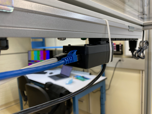
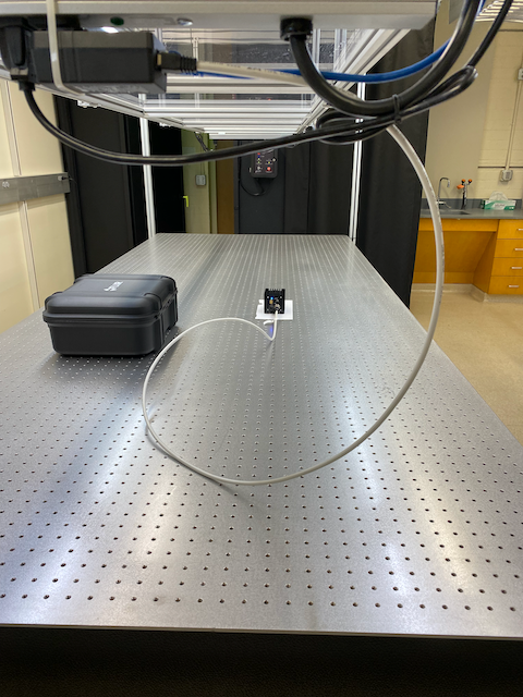
Since everything appears to be working, I ran a permanent Cat 6 cable from the lab switch to the camera's power+I/O adapter. The adapter is plugged into a UPS-protected power strip overhanging the optical table, as pictured below. To prevent the adapter from unplugging itself under its own weight, I attached a zip tie around the adapter to hold it securely in place. |
| Attachment 1: IMG_1480.png
|
|
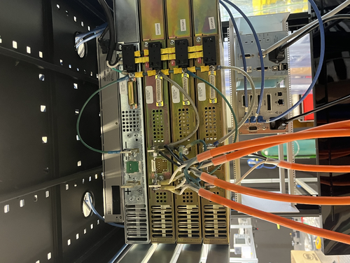
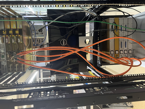
| Attachment 2: IMG_1481.png
|
|
|
243
|
Mon Oct 23 11:28:05 2023 |
Tyler | Update | Cameras | FLIR Camera Code Updates |
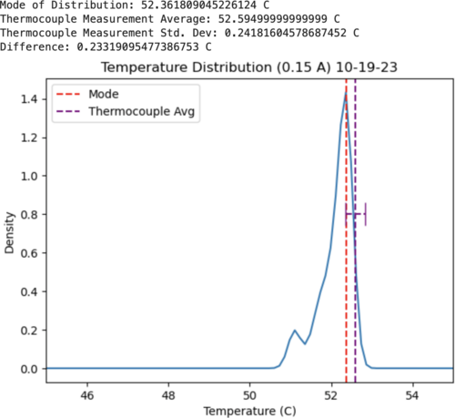
| The past week I've been spending time going through the FLIR code on gitlab. Initially, it had appeared that our measurements with the camera had differed about 2 degrees C from what the thermocouple was giving (Ref ELOG 181). Upon inspection of the FLIR streaming code, I noticed a few issues:
1. The emissivity value wasn't set correctly (was 0.999 originally, should be about 0.95).
2. The ambient temperature was set to about 21.6 C (71 F).
3. The distance given before was about an inch off from what I measured.
These three parameters all must be manually specified to calculate the temperature values, and are what I assume caused the larger temperature difference seen before. I've attached a new set of measurements that I took below, where 6 images were taken by the camera, looking at a heating source with a current of 0.15 A being driven. The difference between the camera and the thermocouple were much smaller, as seen below. I'd still like to take a few more measurements to solidify that this has rectified the issue, but at the moment it seems this is working much better.
Images at: https://drive.google.com/drive/folders/1VDvZ1rfEGWsHq1AgG-chde3Cd8Do_piD?usp=sharing |
| Attachment 1: Screenshot_2023-10-23_at_11.06.04_AM.png
|
|
|
144
|
Tue Jul 4 15:35:38 2023 |
Pamella | Update | FLIR | FLIR - reflexion problem |
| [Pamella]
I was testing all the positions we need to cover when moving the FLIR camera or the reflector. I tried to find out more about the problem so I tested the position without the mask, just with the old bridge and I got the same problems, in the middle of the screen we have a very good image but if we move we have the visualization problem and we don't see the reflection very well (intensity, emissivity) in FLIR.
For this test I used very low current (0.04 A) for keep everything safety.
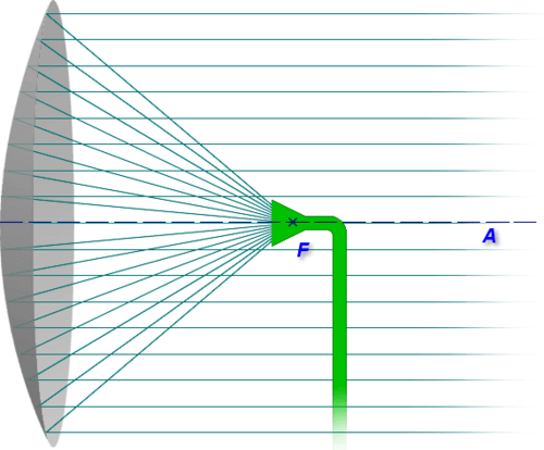
I also think that problem is not in the focal point of the reflector because we can see very well in the center of the screen, but maybe it is because in the parabolic reflector the reflection in the focal point is "extremely" straight, so for you to see the reflection in this point you need keep close to the middle of the screen, to see around the reflector, at the extremes, we need to change the position for the cable or the light to "change" how the flashes of light reflect and thus achieve exactly the position on the camera. It is something like the sketch/ photo attached below. |
| Attachment 1: AcquisitionImage(Jul-03-2023_14_29).jpg
|
.jpg.png)
|
| Attachment 2: AcquisitionImage(Jul-03-2023_14_31).jpg
|
.jpg.png)
|
| Attachment 3: AcquisitionImage(Jul-03-2023_14_49).jpg
|
.jpg.png)
|
| Attachment 4: Caderno_sem_título_(26)-2.jpg
|
-2.jpg.png)
|
| Attachment 5: parabol1.print.png
|
|
|
127
|
Mon Jun 19 11:20:57 2023 |
Pamella | Update | FLIR | FLIR - Fixed some problems |
[Pamella]
- 08:59 am: Turned on the electronic device (current on) for started taking data.
- 09:37 am: Tried understanding the error in the focal point. I realized the pillars was in the wrong place and because of that we got problems to keep the reflector in the correct position to FLIR focus.
- 09:58 am: Started checking the temperature and the parameters.Changed the pillars to the original position (0.5645m) just for checking with the problem was the pillar in the wrong place.
- 10:06 am: Changed the reflector to point (0.3282m) and now in the correct position for the pillars. Started take snap and collecting data. I moved up and down the reflector for got data to compare later.
- 10:37 am: Used the closest point possible for the reflector in front of the FLIR camera with the correct spot for the pillars.(0.2032m)
- 11:00 am: Started taking snap after kept the current on for a few hours. Parameters: Current: 0.10A , Volt: 1.3V and Temperature: 41.9 C.
- I attached below the snap in the most close point possible, now i can see a better photo and I think a fixed the problem about the focal point in the reflector for have more uniformity between the triangles, isn't perfect yet but now is just some adjustments. Furthermore after that I should be change the reflector position and also the optical focus distance in the FLIR camera and try use the black wall.
|
| Attachment 1: AcquisitionImage(Jun-19-2023_11_00).jpg
|
.jpg.png)
|
|
125
|
Fri Jun 16 16:17:13 2023 |
Pamella | Update | FLIR | FLIR - Change the position |
[Pamella]
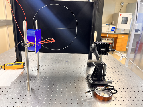
Today I change the distance between the FLIR camera and reflector (3D-Mask with mirrors and light). Now the distance is 0.3282 m.
- Note: In this distance is possible move up and down the reflector and take data to compare.
- The focal point inside the reflector keeping like little problem, every time I tried adjust this I got some triangles is not with "perfect emission" (looks like different than the others). Also if I move up or down the focal point inside the reflector have some issues as well.Therefore I am working on that.
|
| Attachment 1: IMG-7637.jpg
|
|
|
53
|
Wed Mar 22 12:16:20 2023 |
Jon | Infrastructure | Cleanroom | Experimenting with HEPA fan speeds |
Jon, Cao
In effort to try to reduce the noise level inside the cleanroom, we have dialed all four HEPA fan-filter units (FFUs) down from HIGH to MEDIUM speed. These dials can only be accessed from inside the cleanroom, by bringing in the large ladder and opening adjacent ceiling tiles.
We tested three configurations, in each case with all the FFUs on either HIGH (initial state), MEDIUM, or LOW. We measured the ambient noise in each configuration.
| Fan speed |
Noise inside cleanroom (dB) |
Noise outside cleanroom (dB) |
| HIGH |
80 |
70 |
| MEDIUM |
74 |
66 |
| LOW |
71 |
66 |
Going from HIGH to MEDIUM yields the largest improvement, reducing the ambient sound intensity by 6 dB (i.e., by a factor of 4, corresponding to a ~35% reduction in perceived volume).
An additional 3 dB of noise reduction can be achieved by further reducing the fan speeds to LOW. However, even after allowing some extended settling time (few hours), we found the particle counts to be fluctuating right at the threshold zone for ISO Class 5. Thus we dialed the fan speeds back up to MEDIUM with the expectation that this will be sufficient for Class 5 performance.
The cleanroom now needs to be recertified with a fresh round of five-zone particle count measurements. |
|
395
|
Fri Jul 5 14:23:13 2024 |
Liu | Update | Interferometer Simulations | Engineering drawings for straight edge heater element designs for FROSTI |
| Step files and engineering drawings for the straight edge heater element designs have been created in COMSOL and SolidWorks. They are available in the group Git Repo. With those, we will initiate a discussion with the ceramics supplier for an estimate of the feasibility and benefits of the straight edge element over the curved element in terms of manufacturing cost and time. |
|
493
|
Thu Dec 19 12:00:44 2024 |
Luke | Update | VAC | End of bake |
The vacuum chamber has stopped baking.
Current state as of 11:40, 12/19/2024:
The gate valve is open, and the filament of the RGA is on.
The temperatures were steady at:
PID right: barrel upper: 129°C, RGA volume: 125°C
PID left: barrel lower: 125°C, Lid: 114°C
The RGA flange was 37°C
Cleanroom was 26°C
Note the upper barrel was very close to the emergency shut off temp of 130°C. In the future we may want to either rewire some of the heating tape or lower the set temperature of the right PID controller.
Luis and I are planning on taking an RGA scan of the MR on Sunday before the campus shuts down for the holidays. |
|
289
|
Sat Dec 9 12:34:12 2023 |
Jon | Update | General | Electronics workshop migrated to 1129 |
[Jon, Tyler, Shane, Luis]
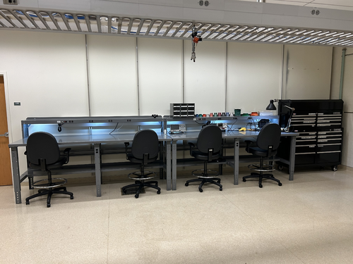
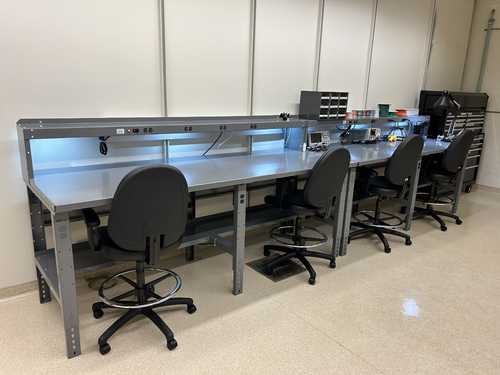
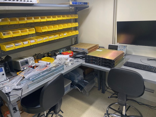
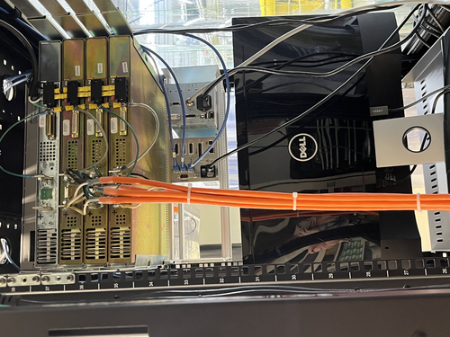
On Wednesday we completed the migration of the electronics workshop from 1119 to the large new workbenches in 1129. The two workstations pictured closest to the front of the room are for electronics assembly and testing, while the two in the rear will house LIGO CDS workstations. We moved all of the tools, cabling, and soldering and test equipment from 1119 to this new location. We also moved the large tool chest to 1129, as pictured, and moved the smaller tool chest to 1119 in its place.
The electronics workbench is ready for use. |
| Attachment 1: IMG_0765.jpg
|
|
| Attachment 2: IMG_0767.jpeg
|
|
|
217
|
Tue Aug 29 22:07:38 2023 |
Aiden | Update | General | Electronic Bench |
| Dr Richardson is working on mounting more power supplies in the server rack and is using the electronics bench. Be aware to not move anything on the bench itself. |
| Attachment 1: IMG_4632.jpg
|
|
|
447
|
Mon Sep 23 15:11:21 2024 |
Tyler | Update | Scripts/Programs | Effective Emissivity Analysis and RIN Update |
A quick update on the effective emissivity analysis for the CIT FROSTI testing:
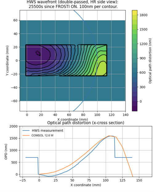
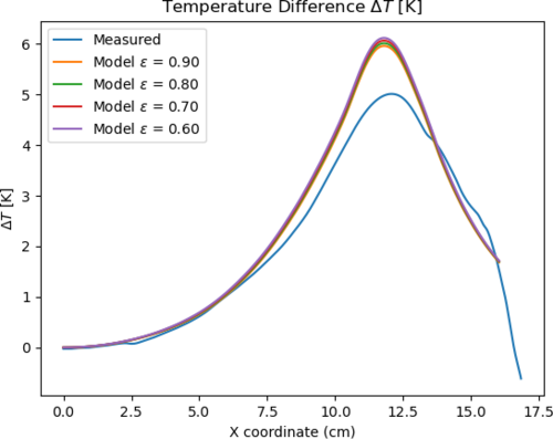
I was able to (roughly) match the OPD data to a referenced COMSOL model, with an applied power of 12.6 W (as seen below). However, when changing the emissivity of the ETM in COMSOL, the dT profiles do not seem to change much. I am not sure as to why this is the case at the moment, and will continue to look further.
Additionally attached are the current RIN measurements of the FROSTI prototype. Shown is the PSDs of both channels, in reference to their individual backgrounds.
|
| Attachment 1: OPD_Plot.png
|
|
| Attachment 2: Temp_emiss_plot.png
|
|
| Attachment 3: rin_photodectors.png
|
|
| Attachment 4: RIN_setup.jpg
|
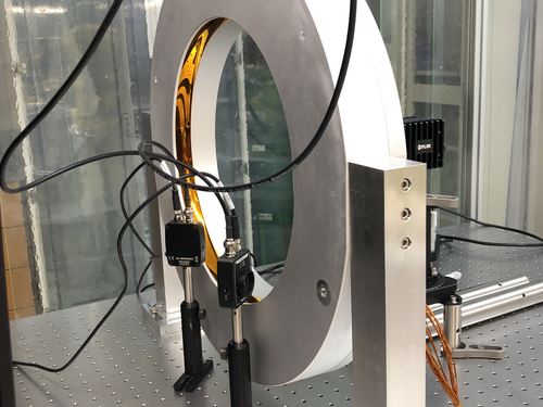
|
|
404
|
Mon Jul 15 09:36:44 2024 |
Liu | Update | Interferometer Simulations | ETM Profile Optimization for FROSTI |
This is to optimize the FROSTI heating profile for ETM, by minimizing the residual RMSE of the HR surface deformation after the beam size weighted curvature is removed by the current RH. The parameters of the profile being explored are the location, width, and total power for the Gaussian Annulus. As shown in the attached series of plots, the optimal location is 9.9 cm, with a width of 7.7 cm, and a total FROSTI power of 12.7 W (for 1 W of Gaussian beam absorption). The residual RMSE is 1.2 nm. About 0.5% of the FROSTI power is lost at the edges of the TM.
For comparison, without FROSTI, the residual RMSE after the beam size weighted curvature removed by the current RH is 44.5 nm. When the width of the Annulus is set to be 3 cm however, the residual RMS is 3.1 nm, with much smaller FROSTI power needed at 4.7 W, and less power loss at 0.02%. |
| Attachment 1: pdf_merged.pdf
|

|
|
332
|
Tue Feb 20 18:08:24 2024 |
Aiden | Update | General | Degassing the RGA |
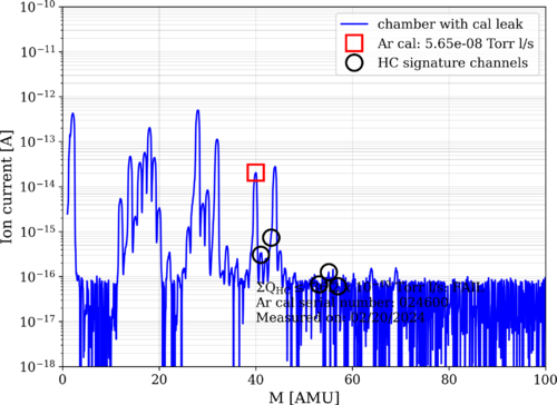
| I took an RGA measurement before and after degassing the RGA. Both data was taken with the Argon open. The pressure before taking data was 2.39 e-8 torr in the main volume. Note that the main chamber was fully valved off for the degas and the main chamber pressure quickly rose to e-6 torr. Further investigation of this rise should be done as this might be the main culprit for the leaking. |
| Attachment 1: bake11_240220_Elements_postdegas_ArO.png
|
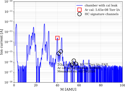
|
| Attachment 2: bake11_240220_Elements_predegas_ArO.png
|
|
|
151
|
Sat Jul 8 14:26:17 2023 |
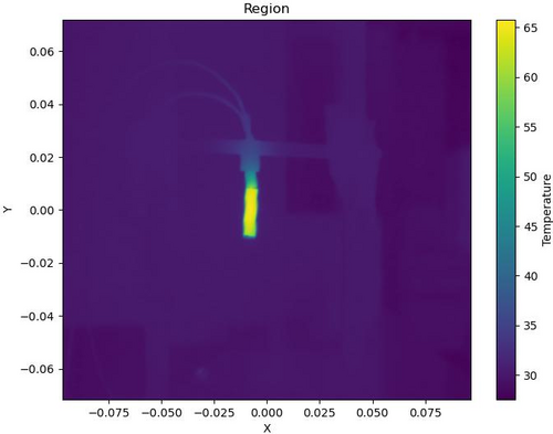
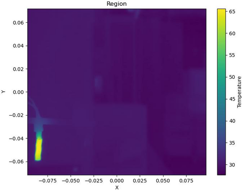
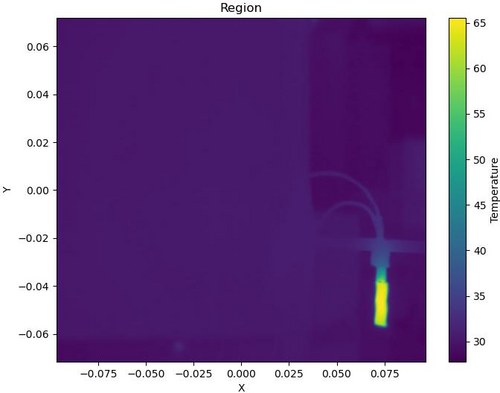
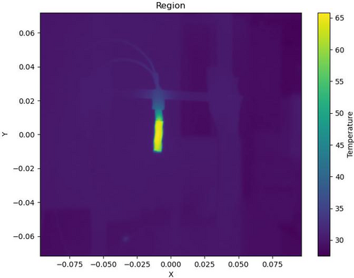
Pamella | Update | FLIR | Data with the new configuration without the mask and reflector. |
| [Pamella]
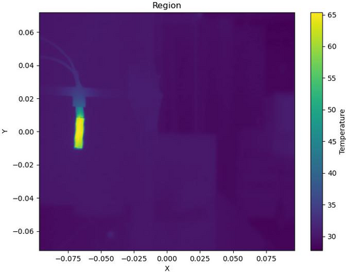
I started collecting data by moving the camera FLIR and covering all six positions on the screen (2x3). I was looking and taking snaps for more than one hour and a half. I'll repeat this one more time to make sure we have enough data to do analysis.
I attached snap data below. This images is processed on python code. |
| Attachment 1: region2-3.jpg
|
|
| Attachment 2: region3-2.jpg
|
|
| Attachment 3: region4.jpg
|
|
| Attachment 4: region5.jpg
|
|
| Attachment 5: region6.jpg
|
|
| Attachment 6: region_temperature1-2.jpg
|
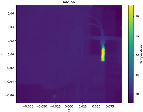
|
|
167
|
Wed Jul 19 19:10:31 2023 |
Pamella | Update | FLIR | Data plot FLIR and updates. |
[Pamella]
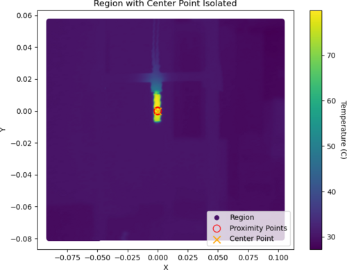
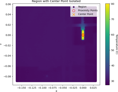
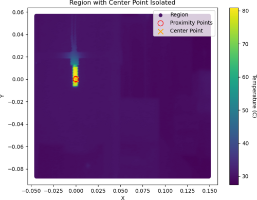
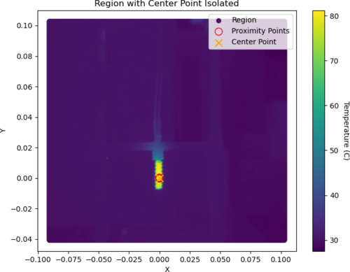
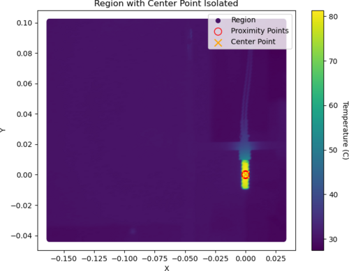
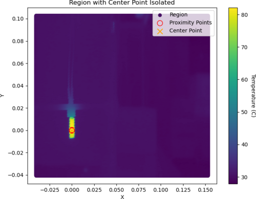
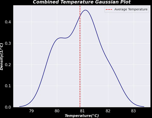
- Today I was able to plot a graph for the isolation point on the center of the heater. I got data from six different positions on the screen (I shifted the all coordinates). I extracted the data for the center point and plot the Gaussian with this extracted data for temperature. I attached the all plots below
- Also I took a snap using the black wall and with the heater at 120.1 C (0.30 A) try to have less noise but
we can see this is not very good. At this temperature, we have noise on the top and I don't understand why because the heater is not in this location. I attached a snap below.
|
| Attachment 1: 1_Isolated_Plot.png
|
|
| Attachment 2: 2_Isolated_Plot.png
|
|
| Attachment 3: 3_Isolated_Plot.png
|
|
| Attachment 4: 4_Isolated_Plot.png
|
|
| Attachment 5: 5_Isolated_Plot.png
|
|
| Attachment 6: 6_Isolated_Plot.png
|
|
| Attachment 7: Gauss.plot-2.jpeg
|
|
| Attachment 8: AcquisitionImage(Jul-19-2023_17_01).jpg
|
.jpg.png)
|
|
169
|
Thu Jul 20 21:00:23 2023 |
Pamella | Update | FLIR | Data plot FLIR and updates about the black body |
[Pamella]
- Today I got more data to plot the Gaussian. So I took more snaps in each position for the six different spots than we be using to have a better calibration of the FLIR collected data. I attached the new plot below. Also, I did the same plot for each region as on the Elog 167 but I have more than 20 pics because I was using a big number of data so I just attached one example below.
To access the Elog, click here.
- Also I think we have some real (non-ideal) heat diffusion by the screen and not noise like Dr. Richardson suggested. I was testing today and we can see the first pic before the start heater source turns on, the second pic is at 120.2 C (0.31A) with the heater on and the last pic is after the heater source cooled back down to room temperature. Just in the second pic, we have a strong spot on the top, so it looks like a non-ideal diffusion.
|
| Attachment 1: AcquisitionImage(Jul-20-2023_13_09).jpg
|
.jpg.png)
|
| Attachment 2: AcquisitionImage(Jul-20-2023_13_15).jpg
|
.jpg.png)
|
| Attachment 3: AcquisitionImage(Jul-20-2023_13_33).jpg
|
.jpg.png)
|
| Attachment 4: AcquisitionData-480(Jul-20-2023_SIsolated_Plot.png
|
|
| Attachment 5: Gauss.plot-2.jpeg
|

|
|
139
|
Fri Jun 30 15:57:28 2023 |
Pamella | Update | FLIR | Data and python code update |
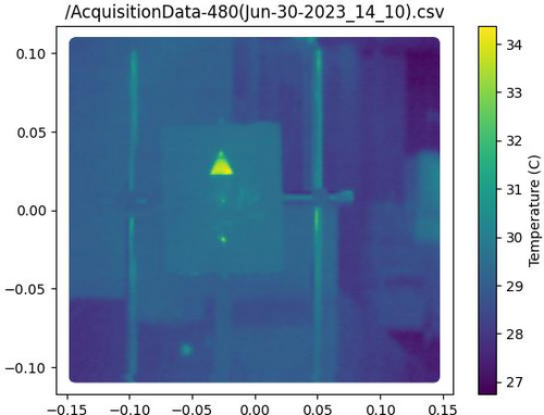
Updates: Problems with the emission intensity and python code.
- Yesterday I was working on get data from FLIR reflector but unfortunately we got some problems:
- I realized than if I move the reflector a to left or right the screen doesn't get data very well(I attached a photo below). This is a problem because our idea is have the same type of emission every part on screen. Tyler and I worked to tried fix that but don't had success.
- Dr. Richardson gave me the idea to move the FLIR camera to left or right (The same happens if I move up and down) and keep the refletor on the same position every time but unfortunately we got the same problem, the screen doesn't get data very well(I attached a photo below). Now I am working to tried fix that.
- Also I was able to work on the code to isolate the triangle shape for analyzes, I attached the image for that below.
|
| Attachment 1: isolation1-2.jpg
|
|
| Attachment 2: AcquisitionImage(Jun-29-2023_18_27)_(1).jpg
|
_(1).jpg.png)
|
| Attachment 3: AcquisitionImage(Jun-29-2023_18_38).jpg
|
.jpg.png)
|
| Attachment 4: AcquisitionImage(Jun-29-2023_18_39).jpg
|
.jpg.png)
|
|
276
|
Wed Nov 22 15:46:50 2023 |
Shane | Update | CDS | DB25 signal connections for FROSTI heaters |
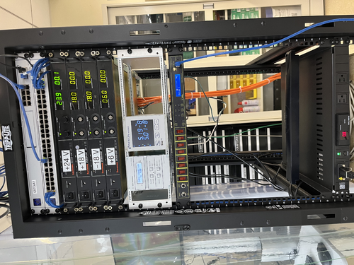
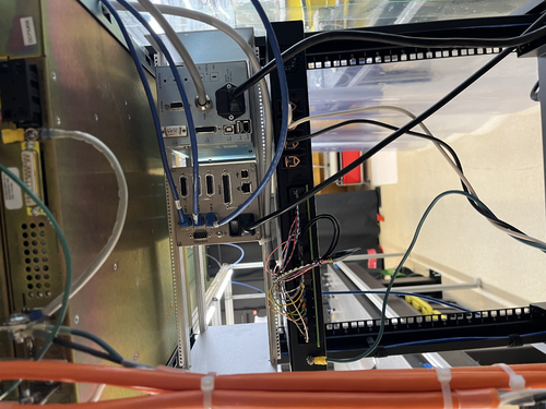
[Shane, Jon]
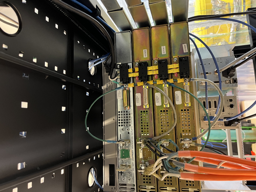
Installed new DC smart switch in electronics rack, configured power connections. Images attached. Attached is a diagram of the male DB25 signal connections to be used for FROSTI heaters. Also included below is table detailing pin and signal configuration.
| Pin |
Signal |
| 1 |
V+ Heater 1 |
| 2 |
V+ Heater 2 |
| 3 |
V+ Heater 3 |
| 4 |
V+ Heater 4 |
| 5 |
V+ Heater 5 |
| 6 |
V+ Heater 6 |
| 7 |
V+ Heater 7 |
| 8 |
V+ Heater 8 |
| 9 |
N/C |
| 10 |
N/C |
| 11 |
N/C |
| 12 |
N/C |
| 13 |
N/C |
| 14 |
RTN heater 1 |
| 15 |
RTN heater 2 |
| 16 |
RTN heater 3 |
| 17 |
RTN heater 4 |
| 18 |
RTN heater 5 |
| 19 |
RTN heater 6 |
| 20 |
RTN heater 7 |
| 21 |
RTN heater 8 |
| 22 |
N/C |
| 23 |
N/C |
| 24 |
N/C |
| 25 |
N/C |
|
| Attachment 1: DB25input_signals.pdf
|

|
| Attachment 2: IMG_3137.jpeg
|
|
| Attachment 3: dc_smart_switch_signal_connections.jpeg
|
|
|
277
|
Thu Nov 23 12:34:44 2023 |
Jon | Update | CDS | DB25 signal connections for FROSTI heaters |
Update: I was able to put the FROSTI power controller on the lab network. It is connected to the switch in the top of the rack and is assigned a static IP address of 192.168.1.12 and an NDS hostname of relay1.
The controller can be remotely accessed through an SSH command line interface as well as an HTML webpage, which can be opened from any web browser on the lab network by navigating to the above IP address (the login credentials are the same as for the workstation computers).
There is also an unofficial Python package for interfacing with the controller: dlipower. We will investigate using this package to interface the controller with soft EPICS channels hosted on the CyMAC. This will allow us to create a custom MEDM screen for controlling the FROSTI heater elements.
Edit: The login credentials were set up to be the same as for the CDS workstations. |
|
290
|
Mon Dec 11 12:58:57 2023 |
Shane, Luis | Update | CDS | DAC-ADC loopback test debugging |
| [Luis, Shane]
Working on debugging last week's weird results for the ADC-DAC loopback test for channels 14 and 15. With DAC output channels 12-15 connected to ADC input channels 12-15: tried setting matrix coefficients for channels 12-15 to 1, and as with last week's results, DAC is outputting as expected for all three channels and ADC is not reading in the signal (hovering around -4,-5) for channels 14 and 15. Channels 12 and 13 still reading in correctly. Tried switching DAC output plug into channels 0-3, with ADC input plugged into channels 12-15, and all input/output signals were reading correctly. Then switched to plugging in DAC output to channels 12-15 and ADC input to channels 0-3, and saw that channels 0-3 were only able to receive the first two ADC input values. This shows that channels 12-15 are capable of receiving the correct inputs from other channels, but are failing to produce outputs for channels 14 and 15. |
|
434
|
Tue Sep 3 18:24:17 2024 |
Tyler | Update | CDS | Cymac Timing Chassis Issue |
| [Tyler, Jon]
The timing chassis used for the cymac has been shut off due to an unknown issue causing its supplied current to fluctuate. All real-time models will be suspended until a solution is found.
|
|
610
|
Mon Jul 14 23:50:22 2025 |
Tyler | Update | | Cymac ADC update |
I've been looking into the performances of individual channels on the Cymac by computing their individual PSDs and corresponding CSDs that show their noise relation to each other. It appears some channels do have lower noise floors than others, and some combinations of these actually do perform similar to the Red Pitaya (showing below the CSD between CHs 3 and 5), although it doesn't look like it's much of an improvement. The best method as of now still appears to be phase-locking two separate ADCs to reduce the correlated noise floor further.
This can be further discussed at the July 22, 2025 group meeting. |
| Attachment 1: cymac_ADC_PSDs.pdf
|

|
| Attachment 2: ch35_ADC_comps.pdf
|

|
|
570
|
Tue May 6 12:25:03 2025 |
Tyler | Configuration | CDS | Cymac ADC CSD measurement |
| An initial measurement of the cymbal ADC CSD is attached below. As of now, it seems that the sensitivity limit is roughly the same as that of the Red Pitaya. |
| Attachment 1: cymac_adc_rin_v1.pdf
|

|
|
265
|
Mon Nov 13 11:23:54 2023 |
Jon | Update | CDS | CyMAC testing |
[Jon, Shane, Luis]
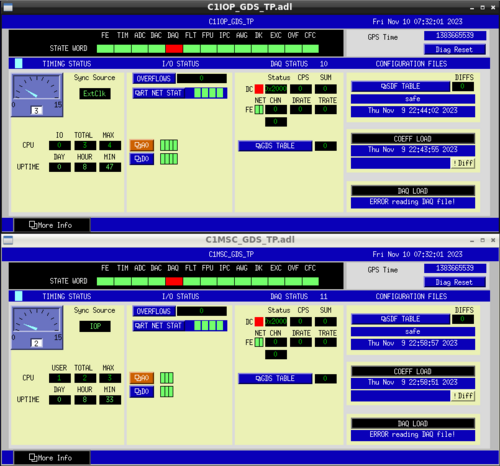
My repair of the internal ribbon connecting the ADC to the adapter board resolved the timing signal problem. After this repair, we were able to start the front-end IOP model and checked out the RTS diagnostic screens (pictured below). All indicator lights were green except for the DK flag (indicating the DAC outputs are not enabled) and the DAQ flag (indicating that the system is recording data to disk). Those were both as expected, because the DAQD data acquisition service was not set up yet and the DAC outputs are not enabled until at least one user model (which outputs signals to the DAC) is started. I created and installed a simple user model (C1MSC) and confirmed that the DK flag clears once this model starts.
I later attempted to set up the DAQD service, which is needed to save data, but am yet to successfully debug it. I have received some guidance from one of LIGO's CDS experts and will try it at my next opportunity for lab work. |
| Attachment 1: Cymac_GDS_Diagnostics.png
|
|
|
254
|
Thu Nov 2 17:14:36 2023 |
Shane, Jon | Update | CDS | CyMAC set up permanentized |
|
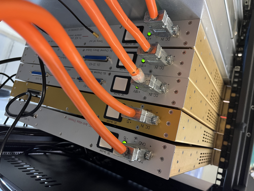
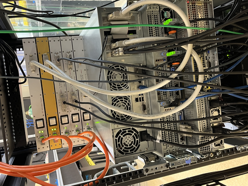
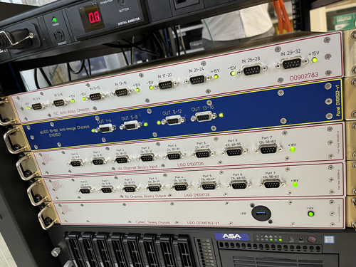
CyMAC connections have been finalized and made permanent. Also tested voltages, which are all looking good. Warning: power is on. Do not touch power supply terminals or screws connected to grounding cables (see attached images 4 and 5; green wires on back of power supply with black and yellow covers, and exposed positive and negative terminals on back of power supply).
Also established connections from Anti-Aliasing chassis to ADC adapter board, Anti-Imaging chassis to DAC adapter board, and binary in/out chassis to BIO card, all mounted within Cymac host computer. Turned on CyMAC and ran test model, received error message likely pointing to timing signal not being successfully passed to the adapter boards. Next steps are checking to make sure correct timing signal is actually being output, and then checking internal ribbon cable in host chassis, which is another potential cause of the error.
|
| Attachment 1: cymac_chassis_back.jpeg
|
|
| Attachment 2: cymac_chassis_back2.jpeg
|
|
| Attachment 3: cymac_chassis_front.jpeg
|
|
| Attachment 4: final_connections_back_of_power_supply.jpeg
|
|
| Attachment 5: power_supply_back.jpeg
|
|
|
250
|
Mon Oct 30 18:15:13 2023 |
Shane | Update | CDS | CyMAC chassis mounted and progress on power connections |
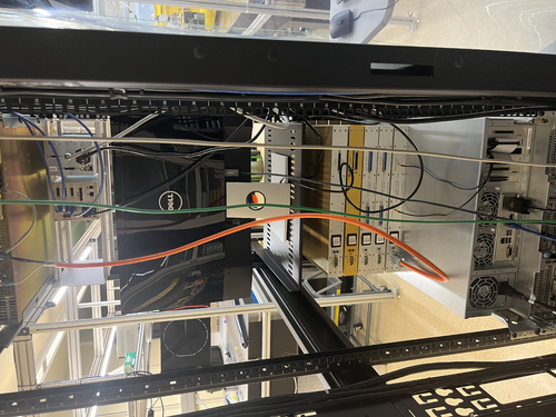
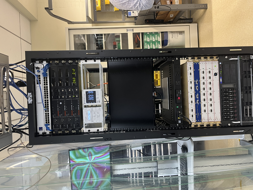
| All CyMAC chassis mounted in electronics rack today, and shelf for monitor also mounted. Images attached. Assembled grounding cables for power connections, and attached the timing chassis to power & gnd. Powered on successfully with correct voltages in expected places. After power test, everything was turned off and unplugged. Next steps: attach grounding cables to other four power supply chassis. Also attach anti-aliasing, anti-imaging, binary input and binary output chassis to power supply. |
| Attachment 1: electronics_rack_back.jpeg
|
|
| Attachment 2: electronics_rack_front.jpeg
|
|
| Attachment 3: mounted_chassis.jpeg
|
|
| Attachment 4: power_supply.jpeg
|
|
|
Draft
|
Tue Oct 1 19:41:23 2024 |
Shane | Update | CDS | CyMAC Timing Chassis Issue |
| [Shane, Luis]
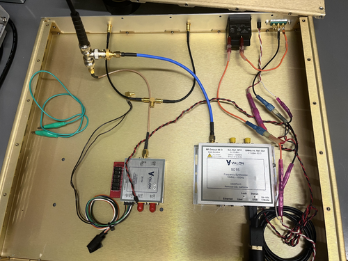
Summary of the issue we've been having with the timing chassis: when we connect only the Valon 5015 to power, the timing signal comes out of it sinusoidal as expected and the status lights are steady and all looks good. As soon as we connect the 3010 to power, the signal (both coming out of the 5015 and coming out of the 3010) go flat and the status lights of the 5015 start to flicker.
We think what may be going on is that the 5015 is drawing just enough power to survive on its own, but when the current gets split to go to the 3010 as well, the 5015 takes more than it needs and becomes overpowered, and thus no longer outputs anything. We want to test further by powering them with two separate power supplies, but we need another one of the power connectors for the 3010 (the only one we have branches out from the connector to the 5015 and we don't want to cut any of the wires).
Images of the inside of the chassis, along with two roughly sketched circuit diagrams (one showing the current setup, in which they're powered by the same source, and one showing a possible test set up, in which they're powered separately. |
| Attachment 1: IMG_5917.jpeg
|
|
| Attachment 2: IMG_5803.jpeg
|
|
| Attachment 3: IMG_5804.jpeg
|
|
|
252
|
Wed Nov 1 18:24:01 2023 |
Shane | Update | CDS | CyMAC Power connections made |
Finished power connections today for the CyMAC chassis. Images attached. Had to switch the shrink fork terminals on the power supply cables to shrink ring terminals, but was able to get everything connected and secured. Upcoming work: turning on power supply and testing voltages/checking everything is turning on and lighting up correctly.
Configuration is as follows:
- Topmost Sorensen: +24V (reserved for FROSTI)
- Negative terminal: [negative terminal is grounded]
- jumper to Sorensen ground screw
- Sorensen 2nd from the top: +18V
- Positive terminal:
- white power cable wire for AA chassis
- white power cable wire for AI chassis
- white power cable wire for BI chassis
- white power cable wire for BO chassis
- Negative terminal: [negative terminal is grounded]
- jumper to Sorensen ground screw
- black power cable wire for AA chassis
- black power cable wire for AI chassis
- black power cable wire for BI chassis
- black power cable wire for BO chassis
Sorensen 3rd from the top: -18V
- Positive terminal:[positive terminal is grounded]
- jumper to Sorensen ground screw
- green power cable wire for BI chassis
- green power cable wire for BO chassis
- Negative terminal:
- green power cable wire for AA chassis
- green power cable wire for AI chassis
Bottommost Sorensen: +6V
- Positive terminal:
- white power cabe wire for timing chassis
- Negative terminal: [negative terminal is grounded]
- jumper to Sorensen ground screw
- green power cable wire for timing chassis
- black power cable wire for timing chassis
|
| Attachment 1: cymac_power_connected.jpeg
|
|
| Attachment 2: cymac_power_connections_back.jpeg
|
|
|
626
|
Tue Aug 12 12:35:19 2025 |
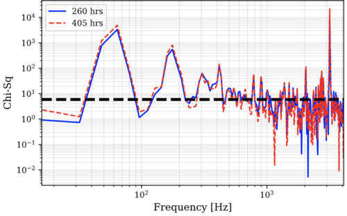
Tyler | Update | | CyMAC ADC Update |
| [Christina, Ma, Tyler]
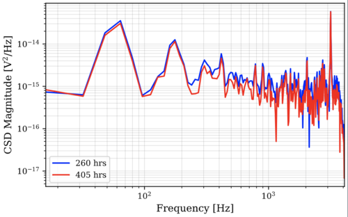
Updated CyMAC measurement, comparing 260 hrs of measurement time vs. 405 hrs. |
| Attachment 1: CSD_magnitude.png
|
|
| Attachment 2: chi_sq.png
|
|
|
607
|
Tue Jul 8 12:15:04 2025 |
Tyler | Update | TCS | CyMAC ADC Noise Update |
| [Tyler, Christina, Ma, Mary]
Below is attached the ADC noise floor of two CyMAC channels vs the Red Pitaya.
The frequency resolution of these RIN spectra are 16 Hz, with N_meas = 19,308,426 for the CyMAC, and N_meas = 263,024. |
| Attachment 1: ADC_comps.pdf
|

|
|
595
|
Tue Jun 17 12:46:47 2025 |
Tyler | Update | Electronics | CyMAC ADC Noise |
| Below are results from power spectra measurements of the CyMAC ADC, computed form 30 hours of time series data, compared to the performance of the Red Pitaya. The frequency resolution for the initial Cymac CSD is 2 Hz, and 216,000 spectra measurements are averaged together. As of now, it still looks like we haven't reached the correlated noise floor of the CyMAC. We have a few days worth of data to take from, so I'll look into using a longer period of time. |
| Attachment 1: cymac_v_rp_csds.pdf
|

|
| Attachment 2: chi_sq_cymac_v_rp.pdf
|

|
|
2
|
Thu Jun 2 16:14:58 2022 |
Jon | HowTo | General | Custom conda environment on JupyterHub |
Cross-linking instructions: How to run a Jupyter notebook in your custom Conda environment |
|
374
|
Mon Jun 3 14:59:44 2024 |
Cynthia | Update | Interferometer Simulations | Created cavity scan with LG modes |
|
| Attachment 1: ligo_update_6_3.pdf
|

|
|
141
|
Mon Jul 3 14:32:24 2023 |
Cao | Infrastructure | VAC | Cooling down vacuum chamber |
| [Cao]
After leaving the the chamber to bake at 120 deg C from Thursday 3:41 pm. Today I started to cool the chamber down to room temperature at 11:30 am (total bake duration: 91 hours 49 minutes). Ideally, this process should be ramped down slowly, approx. 6 degree per hour. However we had no ramping function with out controller. The only method to tune this cool/ heat rate is to tune the PID parameters, which are:
- Pb : Proportional band, this quantity is inversely proportional to the P-gain
- ti : Integral time. Increasing integral time makes the output response slower to error, thus the opposite effect of increasing integration gain
- td : Differential time
Since the differential term doesn't contribute to rise time significantly, we neglect it for now and first change Pb and ti . The factory default settings :
- Pb : 50
- ti : 100 s
- td : 25 s
Initially Ichanged Pb from 50 to 200 (max) and ti to 999 s (max) but there is a large offset error. Currently, Pb and ti are sitting on the following settings:
- Pb : 200
- ti : 800 s
At this setting it takes 25-30 mins to drop 6 degrees, which is not as slow as we want but we will have to tune our PID more carefully.
At the first stage, I dropped the temperature to 60 deg C. After 3 hours, we dropped the setpoint to 25 degrees and let the vacuum chamber to cool to room temperature. |
|
8
|
Fri Jul 22 13:20:28 2022 |
Phoebe | Update | | Comsol |
| I will be using comsol until 1:30 pm today. I will be updating the model for the heater mount to be thicker in certain areas, so that it can feasibly be 3D printed. Specifically, the radius of the center cartridge mount has been increased to add thickness to the pipe and the arms of the bridge. This will allow us to print with a much smaller chance for error, as the printer can print objects with a minimum length of 1 mm. |
|
382
|
Mon Jun 24 21:38:25 2024 |
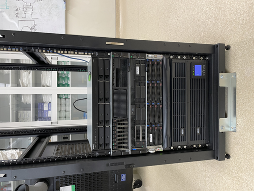
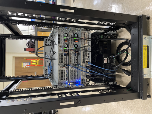
Pooyan | Infrastructure | Computers | Computer server changes in 1119 and 1129 |
[Jon, Pooyan, Tyler]
A few computer machine changes have been made.
- Logrus moved from 1119 to 1129. It is up and running with the same IP address as before.
- A new Windows machine (host name: spica, IP:192.168.1.14) is installed in the 1119 server rack. It is connected to the RGA scanner with the serial port and is specifically used for that purpose.
- Update: The machine was off on 6/25, although it was left on 6/24. We think that it might have been because of Windows' default setting to suspend/hibernate the machine after idleness. To resolve this, I used "powercfg /change" command to set all the following parameters equal to zero. The machine is still running on 6/26.
    monitor-timeout-ac
    monitor-timeout-dc
    disk-timeout-ac
    disk-timeout-dc
    standby-timeout-ac
    standby-timeout-dc
    hibernate-timeout-ac
    hibernate-timeout-dc
-
A new Debian machine (hostname: megatron, IP:192.168.1.16) is installed in the 1129 server rack. This machine is intended to be used for FEA/simulation work. A new 2TB WD Green SSD is used as its main disk drive.
At the moment, “controls” is the only user, and there are no apps/libraries installed on the machine.
- Update: Jon installed LIGO cds-workstation tools and MiniConda on 6/26.
- Update: Pooyan and Liu set the following conda environments:
- Env named “finesse” with Python 3.12.3 and Finesse version 3.0a24 installed. Finesse was installed via the source code. The subdirectory “/home/controls/packages” is used to store the package sourcecodes.
- Env named “fenicsx” with the same version of Python and Finesse as the previous env, with the latest version of FEniCSx (0.8) and the test-mass-thermal-state installed.
|
| Attachment 1: IMG_6889.jpg
|
|
| Attachment 2: IMG_6890.jpg
|
|
|
132
|
Fri Jun 23 15:47:06 2023 |
Pamella | Update | FLIR | Collecting data - Moving horizontal and vertical on screen. |
[Pamella]
- 02:09 pm: Turned on the device (current on)
- 02:42 pm: Started taking snap on position one (Reference point: 0,-0.062). Parameters:0.10A,1.5V,41.5C
- I took multiplier snap on the same position for compare after on data analyzes. I just wanted one/two minute break between the snaps. I did that same for every position.
- 02:55 pm: Started taking snap on position two (Reference point:-0.10,-0.062 ). Parameters: 0.10A,1.5v,43 C
- 03:01 pm: Started taking snap on position three (Reference point:0.05 ,-0.062). Parameters: 0.1A,1.4V,42.8C
- 03:07 pm: Started taking snap on position four (Reference point: 0.05,0.045). Parameters:0.10A,1.5V,43.6 C
- 03:15 pm: Started taking snap on position five (Reference point: 0,0.045). Parameters:0.10A, 1.4V, 44.1C
- 03:22 pm: Started taking snap on position six (Reference point: 0,0.045). Parameters: 0.10A,1.4V,43.3 C
- We can see in the photos attached below than have some differences between every position so I should be starting analyzes on that.
|
| Attachment 1: AcquisitionImage(Jun-23-2023_14_42).jpg
|
.jpg.png)
|
| Attachment 2: AcquisitionImage(Jun-23-2023_14_57).jpg
|
.jpg.png)
|
| Attachment 3: AcquisitionImage(Jun-23-2023_15_01).jpg
|
.jpg.png)
|
| Attachment 4: AcquisitionImage(Jun-23-2023_15_07)_(3).jpg
|
_(3).jpg.png)
|
| Attachment 5: AcquisitionImage(Jun-23-2023_15_15).jpg
|
.jpg.png)
|
| Attachment 6: AcquisitionImage(Jun-23-2023_15_22).jpg
|
.jpg.png)
|
|
241
|
Fri Oct 20 16:38:02 2023 |
Shane, Aiden | Update | Cleanroom | Cleanrooom cleaning and particle count |
|
[Aiden, Shane]
cleaning cleanroom and particle count
|
|
45
|
Mon Mar 6 18:48:43 2023 |
Pamella | Update | General | Cleanroom update |
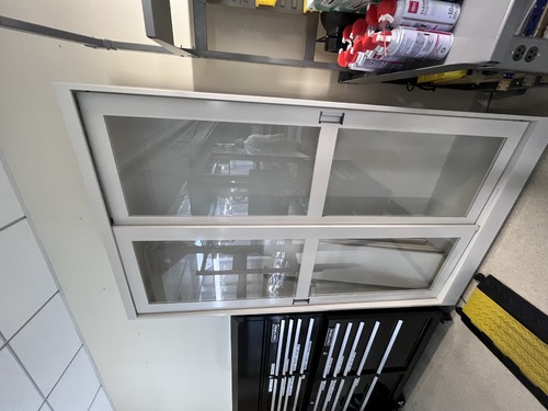
| Today Pamella and Julian finished cleaning of the new lab cabinets. Also we wiped the computer and put inside the cleanroom so now the computer is not move out side anymore.
We saw some dirty parts in the cleanroom floor again and is possible for the next step we should be clearing the floor one more time.
Possible is necessary order more IPA wipes for keep cleaning in nexts weeks.
A photos of the cabinets and the computer are attached below. |
| Attachment 1: 203863E0-106A-465E-8D9C-461B0358FB60.jpeg
|
|
| Attachment 2: 779F360D-CAD0-4C49-AE0B-973F97F6D099.jpeg
|
|
| Attachment 3: 276B9F0C-6661-441F-AD34-D79DA61E1FC3.jpeg
|
|
|
93
|
Mon May 8 12:00:03 2023 |
Pamella, Shane, Julian | Update | General | Cleanroom particle counts and cleaning the cleanroom. |
[Pamella,Julian, Shane]
Today we cleaned the clean-room (floor, surfaces) and particle count.
10:00 am: Started particle count.
- Zone 3:
- 0.3u: 1330
- 0.5u: 540
- 1.0u: 415
- Zone 4:
- 0.3u: 290
- 0.5u: 83
- 1.0u: 0
Clean-room:
- 10:30 am: Started wiping down the surfaces inside the clean-room
- 10:41 am: Finished wiping down the surfaces inside the clean-room and Started vacuuming the clean-room.
- 10:58 am: Finished vacuuming the clean-room.
- 11:00 am: Started mopping on the floor.
- 11:20 am: Finished mopping on the floor and started wiping on the floor.
- 11:34 am: Finished wiping on the floor.
- 11:35 am: Started the particle count.
- 11:57 am: Finished the particle count.
- Zone 3
- 0.3u: 997
- 0.5u: 290
- 1.0u: 207
- Zone 4
- 0.3u: 374
- 0.5u: 207
- 1.0u: 207
|
|
268
|
Thu Nov 16 17:12:42 2023 |
Luis, Shane, Mohak | Update | Cleanroom | Cleanroom cleaning and particle count |
|
[Shane, Luis, Mohak]
cleaning cleanroom and particle count
- 3:37 pm: started particle count
- zone 3:
- 0.3 u: 1205
- 0.5 u: 748
- 1.0 u: 249
- zone 4:
- 0.3 u: 1496
- 0.5 u: 748
- 1.0 u: 290
- 3:57 pm: began surface check and wipedown, including softwalls. NOTE: vacuum chamber insulation crumbling at edges, dropping loose flakes. Scatters residue whenever jostled, so wiping it down just releases more. Not enough flakes are being released for it to be a major issue, but definitely something to keep an eye on.
- 4:18 pm: started vacuuming the floor
- 4:29 pm: finished vacuuming the floor
- 4:30 pm: started mopping the floor
- 4:35 pm: finished mopping the floor
- 4:36 pm: started cleaning the buckets
- 4:41 pm: started mopping with IPA wipes
- 4:52 pm: finished mopping with IPA wipes
- 4:52 pm: changed sticky floor mats
- 4:53 pm: started particle count
- zone 3:
- 0.3 u: 3367
- 0.5 u: 1787
- 1.0 u: 914
- zone 4:
- 0.3 u: 1039
- 0.5 u: 498
- 1.0 u: 249
|