|
ligo-ex
ligo-ds
|
| Richardson Lab Experimental Log |
Not logged in |
 |
|
|
 Mon Nov 20 10:10:50 2023, Tyler, Configuration, Electronics, RTD Logic/Schematic Diagrams Mon Nov 20 10:10:50 2023, Tyler, Configuration, Electronics, RTD Logic/Schematic Diagrams  
|
 Fri Dec 29 16:02:27 2023, Jon, Configuration, Electronics, RTD Readout Chassis Fri Dec 29 16:02:27 2023, Jon, Configuration, Electronics, RTD Readout Chassis   
|
 Tue Jan 9 12:08:59 2024, Tyler, Configuration, Electronics, RTD Readout Chassis Update Tue Jan 9 12:08:59 2024, Tyler, Configuration, Electronics, RTD Readout Chassis Update 
|
 Tue Jan 16 12:20:21 2024, Tyler, Configuration, Electronics, RTD Readout Chassis Update 2 Tue Jan 16 12:20:21 2024, Tyler, Configuration, Electronics, RTD Readout Chassis Update 2  
|
|
|
Message ID: 305
Entry time: Tue Jan 16 12:20:21 2024
In reply to: 300
|
| Author: |
Tyler |
| Type: |
Configuration |
| Category: |
Electronics |
| Subject: |
RTD Readout Chassis Update 2 |
|
|
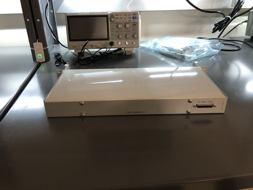
I performed another continuity test on the RTD chassis wiring, and everything seems to be set up correctly. The chassis should be ready for installation.
| Quote: |
Below is the current state of the RTD readout chassis wiring. Initial continuity tests seem good, will run through one more time to confirm.
| Quote: |
The custom front and rear panels for the RTD readout chassis arrived last Friday. I installed them in the chassis frame to check their fit. They fit very well, so all that now remains is to complete the internal wiring and test the connections.
The chassis panel designs are archived to LIGO-D2300452 and LIGO-D2300453.
| Quote: |
|
Below are a basic diagram of what the RTD measurement circuit logically looks like and an example schematic of the actual wiring. The schematic wiring will be placed internally into a chassis, connected to the RTDs via DB25 cable.
Note: The DB25 Breakout Board connector is Female, not Male. |
|
|
|
|
|

|