|
ligo-ex
ligo-ds
|
| Richardson Lab Experimental Log |
Not logged in |
 |
|
|
 Mon Nov 20 10:10:50 2023, Tyler, Configuration, Electronics, RTD Logic/Schematic Diagrams Mon Nov 20 10:10:50 2023, Tyler, Configuration, Electronics, RTD Logic/Schematic Diagrams  
|
 Fri Dec 29 16:02:27 2023, Jon, Configuration, Electronics, RTD Readout Chassis Fri Dec 29 16:02:27 2023, Jon, Configuration, Electronics, RTD Readout Chassis   
|
 Tue Jan 9 12:08:59 2024, Tyler, Configuration, Electronics, RTD Readout Chassis Update Tue Jan 9 12:08:59 2024, Tyler, Configuration, Electronics, RTD Readout Chassis Update 
|
 Tue Jan 16 12:20:21 2024, Tyler, Configuration, Electronics, RTD Readout Chassis Update 2 Tue Jan 16 12:20:21 2024, Tyler, Configuration, Electronics, RTD Readout Chassis Update 2  
|
|
|
Message ID: 298
Entry time: Fri Dec 29 16:02:27 2023
In reply to: 271
Reply to this: 300
|
| Author: |
Jon |
| Type: |
Configuration |
| Category: |
Electronics |
| Subject: |
RTD Readout Chassis |
|
|
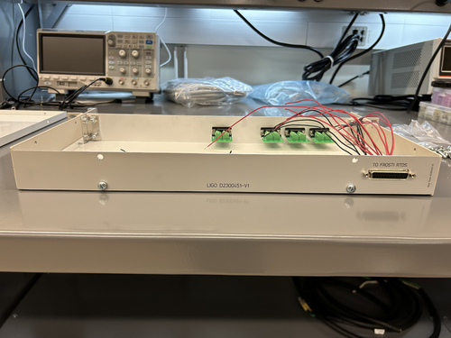
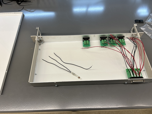
The custom front and rear panels for the RTD readout chassis arrived last Friday. I installed them in the chassis frame to check their fit. They fit very well, so all that now remains is to complete the internal wiring and test the connections.
The chassis panel designs are archived to LIGO-D2300452 and LIGO-D2300453.
| Quote: |
|
Below are a basic diagram of what the RTD measurement circuit logically looks like and an example schematic of the actual wiring. The schematic wiring will be placed internally into a chassis, connected to the RTDs via DB25 cable.
Note: The DB25 Breakout Board connector is Female, not Male. |
|
|
|

|
|

|