|
ligo-ex
ligo-ds
|
| Richardson Lab Experimental Log |
Not logged in |
 |
|
|
 Mon Nov 20 10:10:50 2023, Tyler, Configuration, Electronics, RTD Logic/Schematic Diagrams Mon Nov 20 10:10:50 2023, Tyler, Configuration, Electronics, RTD Logic/Schematic Diagrams  
|
 Fri Dec 29 16:02:27 2023, Jon, Configuration, Electronics, RTD Readout Chassis Fri Dec 29 16:02:27 2023, Jon, Configuration, Electronics, RTD Readout Chassis   
|
 Tue Jan 9 12:08:59 2024, Tyler, Configuration, Electronics, RTD Readout Chassis Update Tue Jan 9 12:08:59 2024, Tyler, Configuration, Electronics, RTD Readout Chassis Update 
|
 Tue Jan 16 12:20:21 2024, Tyler, Configuration, Electronics, RTD Readout Chassis Update 2 Tue Jan 16 12:20:21 2024, Tyler, Configuration, Electronics, RTD Readout Chassis Update 2  
|
|
|
Message ID: 271
Entry time: Mon Nov 20 10:10:50 2023
Reply to this: 298
|
| Author: |
Tyler |
| Type: |
Configuration |
| Category: |
Electronics |
| Subject: |
RTD Logic/Schematic Diagrams |
|
|
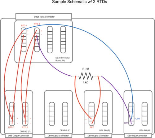
Below are a basic diagram of what the RTD measurement circuit logically looks like and an example schematic of the actual wiring. The schematic wiring will be placed internally into a chassis, connected to the RTDs via DB25 cable.
Note: The DB25 Breakout Board connector is Female, not Male. |
|

|
|

|